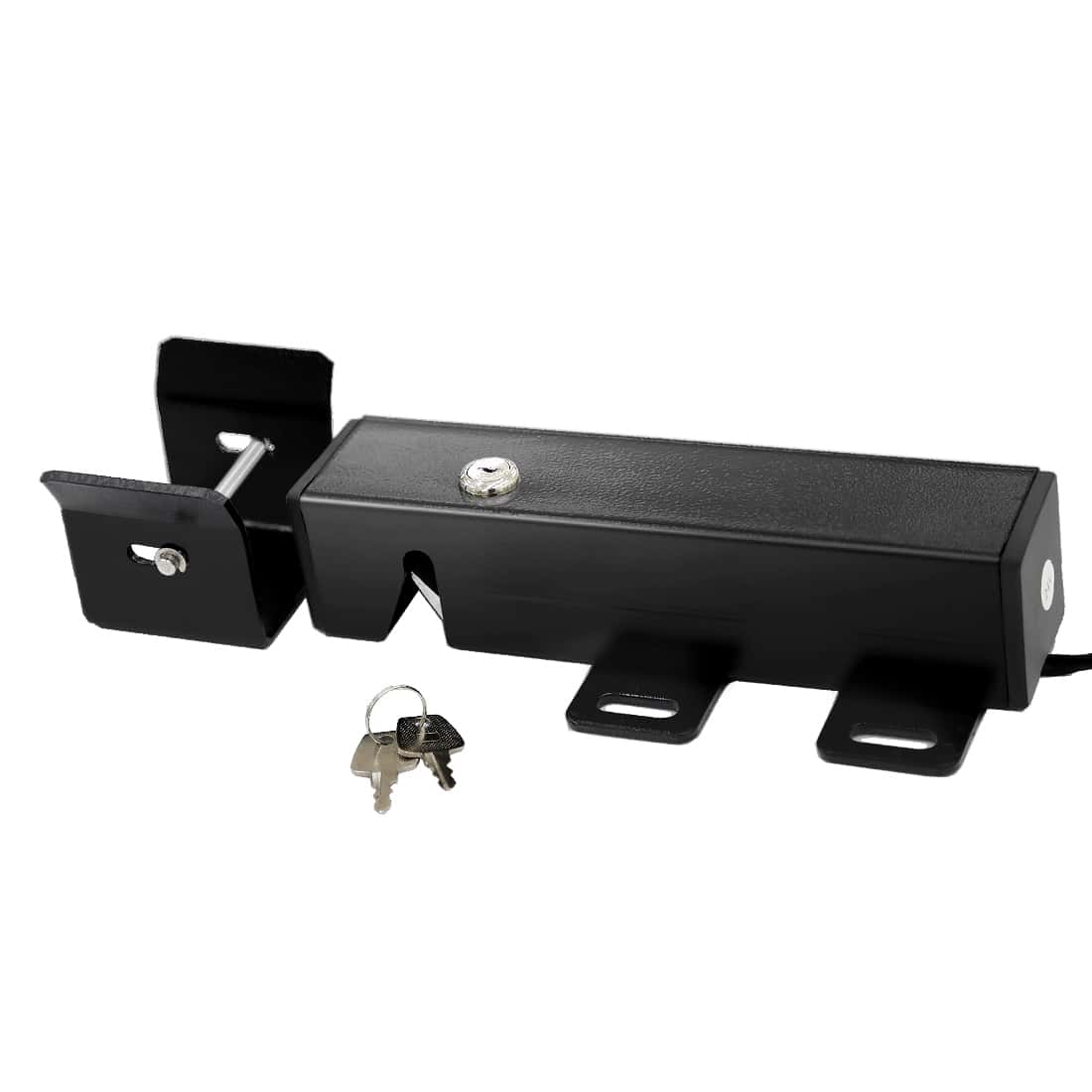
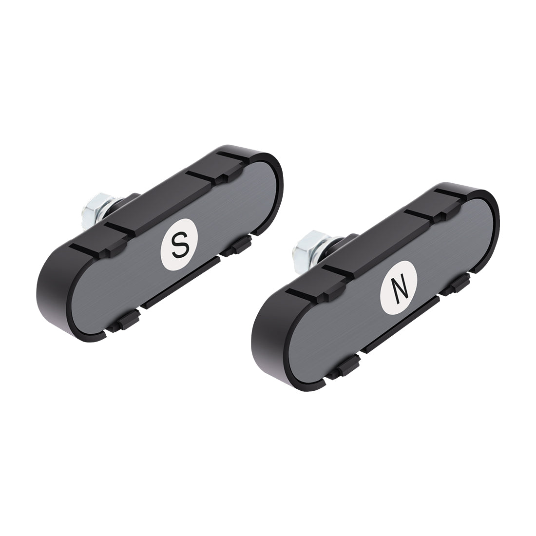
A Knox Gate & Key Switch is an emergency access control device designed for use with automatic gates, electronic access systems, and electrically operated barriers. It allows fire and emergency responders to unlock or activate a gate quickly using a standardized Knox Master Key, providing rapid access without forced entry, property damage, or response delays.
This guide explains how to properly integrate a Knox switch with TOPENS gate openers, including compatibility requirements, wiring methods by model, operating behavior, and key safety and compliance considerations.
1. Compatibility with TOPENS Gate Openers
TOPENS gate openers are compatible with Knox switches that provide a Normally Open (NO) dry contact output. Both momentary and maintained Knox switches may be used, depending on local fire code requirements and site operational needs.
Important: Always verify that the Knox switch provides a dry contact only and does not output voltage. Supplying external voltage to the TOPENS control board may cause damage to the system.
2. Wiring a Knox Switch to TOPENS Gate Openers
(1) General Wiring Overview
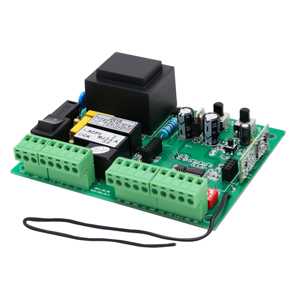
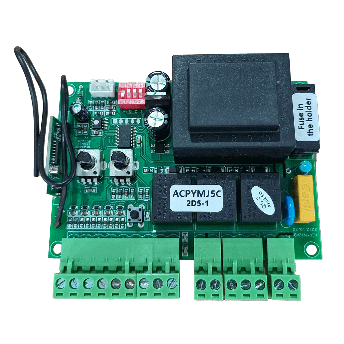
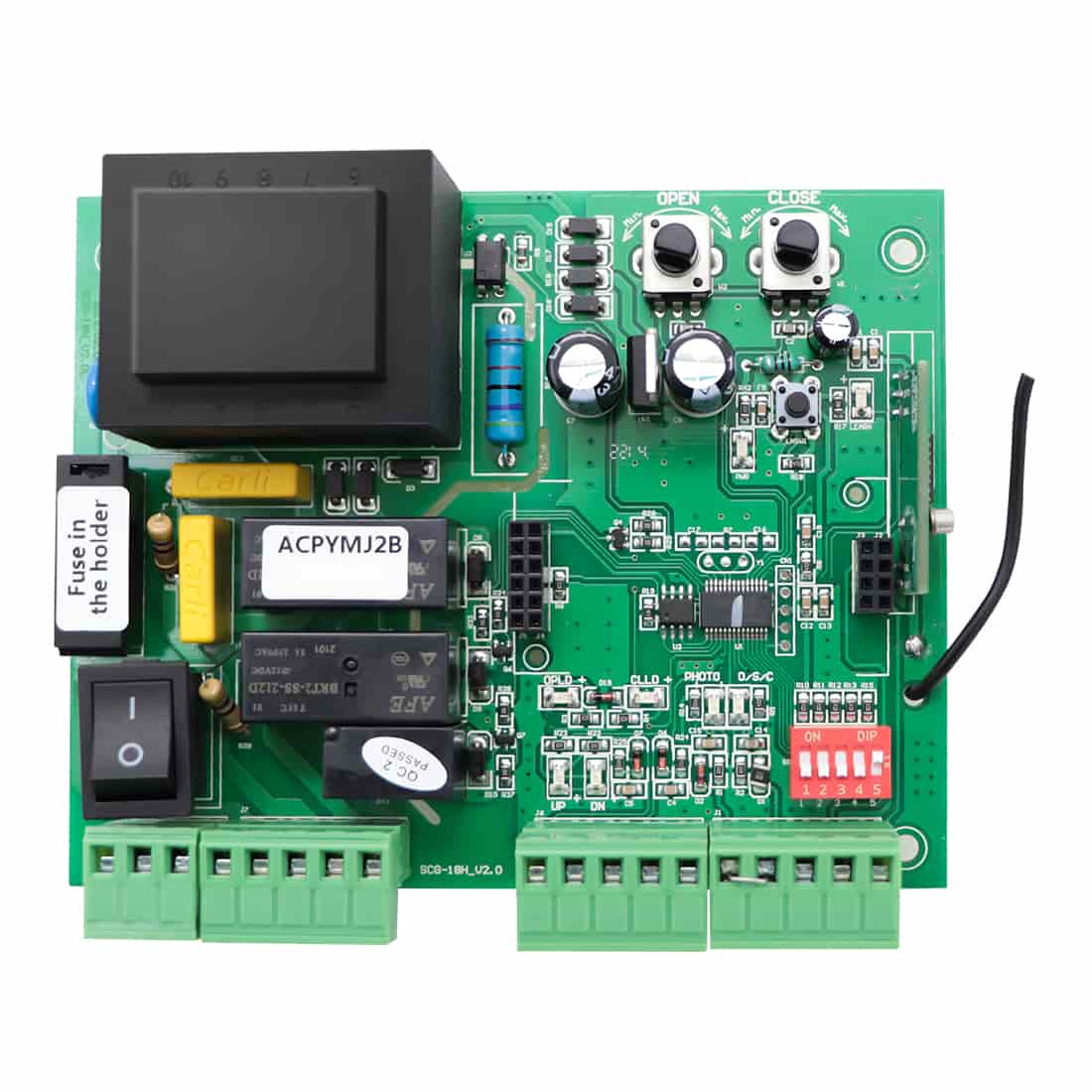
- Most TOPENS swing and sliding gate openers allow the Knox switch to be wired directly to the control board, with no additional interface modules required.
- However, the following models require an adapter board (the same adapter board used with the TOPENS TEW3 Vehicle Sensor Exit Wand): AT602, AT1202, KD702, RK990T, RK1200T, CK1200, RK2500T, CK2500, CK2600.
(2) Wiring Procedure
- For models that require an adapter board, install the adapter board onto the gate opener control board before making any connections.
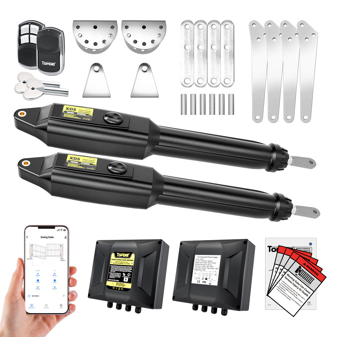
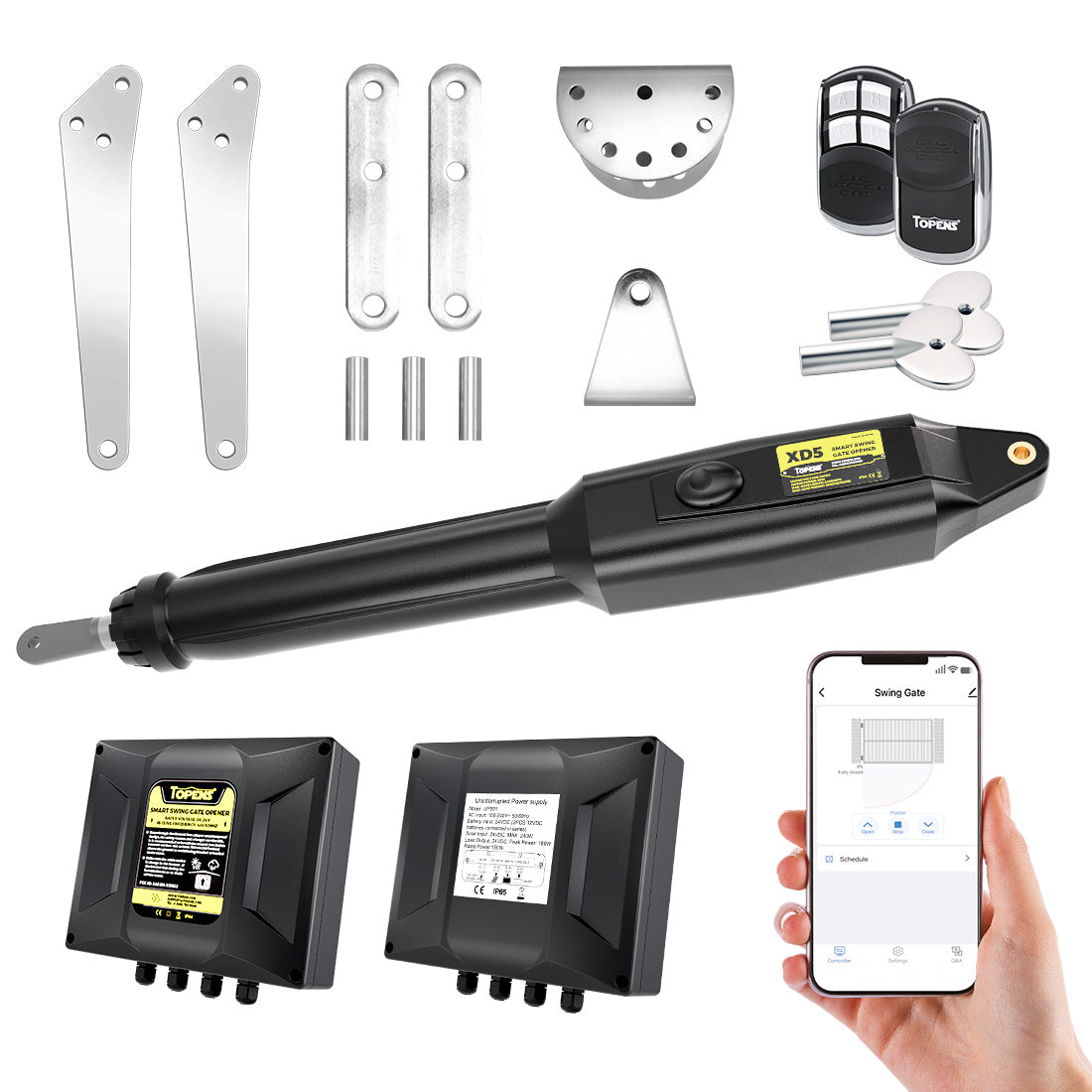
- For models XD852(S), XD552(S), XD851(S), and XD551(S), connect the Knox switch wires directly to the dedicated fire access switch terminals.
- For all other models, connect the Knox switch to the vehicle sensor exit wand terminals on the control board.
(3) Terminal Connections
- Connect the NO terminal of the Knox switch to the opener’s FIRED. / OPSW / LOOP / XB2 terminal.
- Connect the COM terminal of the Knox switch to the opener’s GND / COM / LOOP / OPSW / XB1 terminal.

(4) Connection Reference Chart
Terminal labels may vary by model, but their functions are equivalent. Except for models XD852(S), XD552(S), XD851(S), and XD551(S), which include dedicated fire access terminals, all other models use the vehicle sensor exit wand terminals.
Always refer to the specific TOPENS user manual for exact terminal locations.
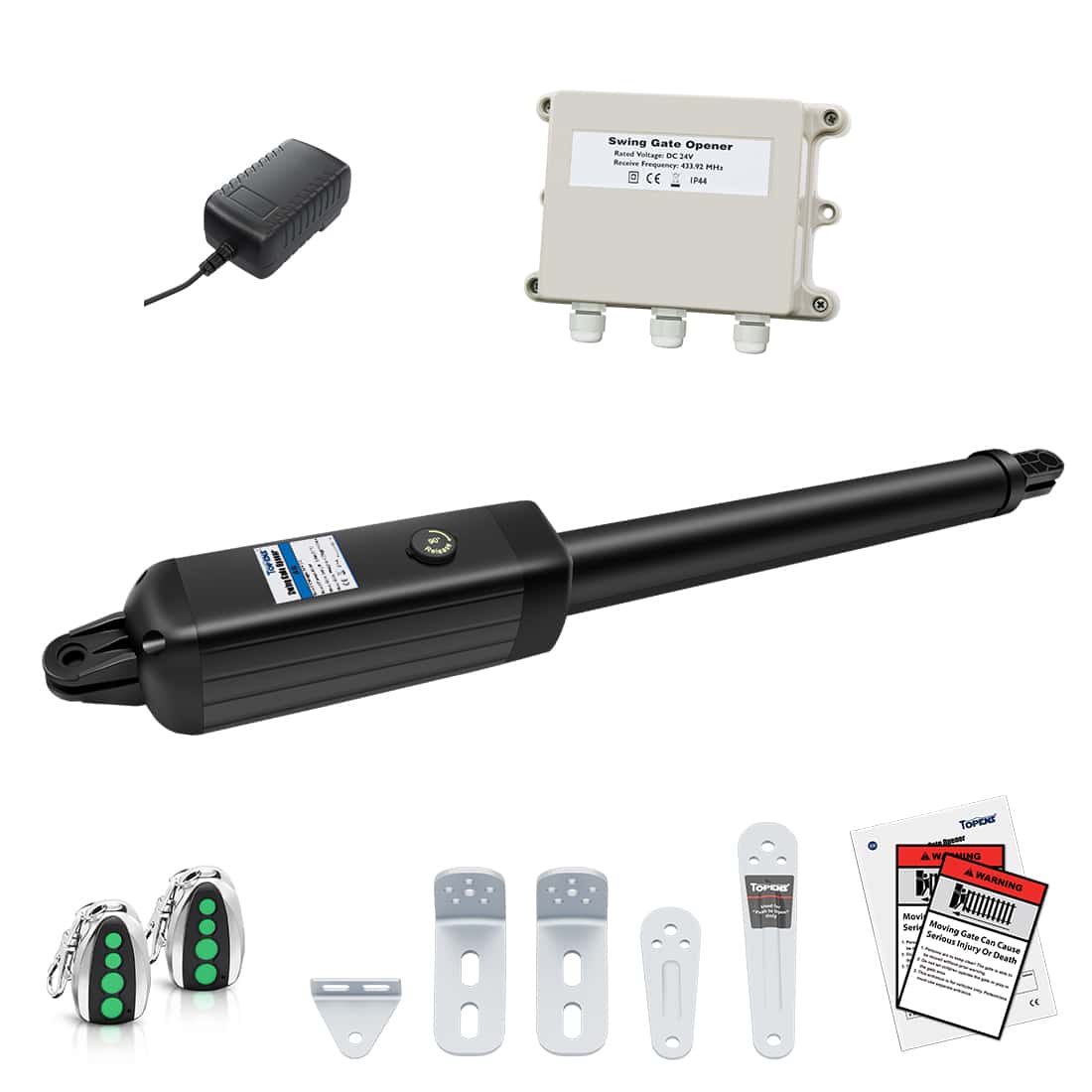
Swing Gate Openers
| Model | Terminals | Connection Type |
| XD852(S), XD552(S), XD851(S), XD551(S) | FIRED. + GND (Dedicated fire access) |
Direct |
| JY9132, AT6132S, AT12132S, A5132, A8132, PW302, PW502, PW802, AD5S, AD8S, AT6131(S), AT12131(S), A5131, A8131, A3S, A5S, A8(S) | OPSW + COM | Direct |
| AT602, AT1202, KD702 | LOOP | Adapter board required |
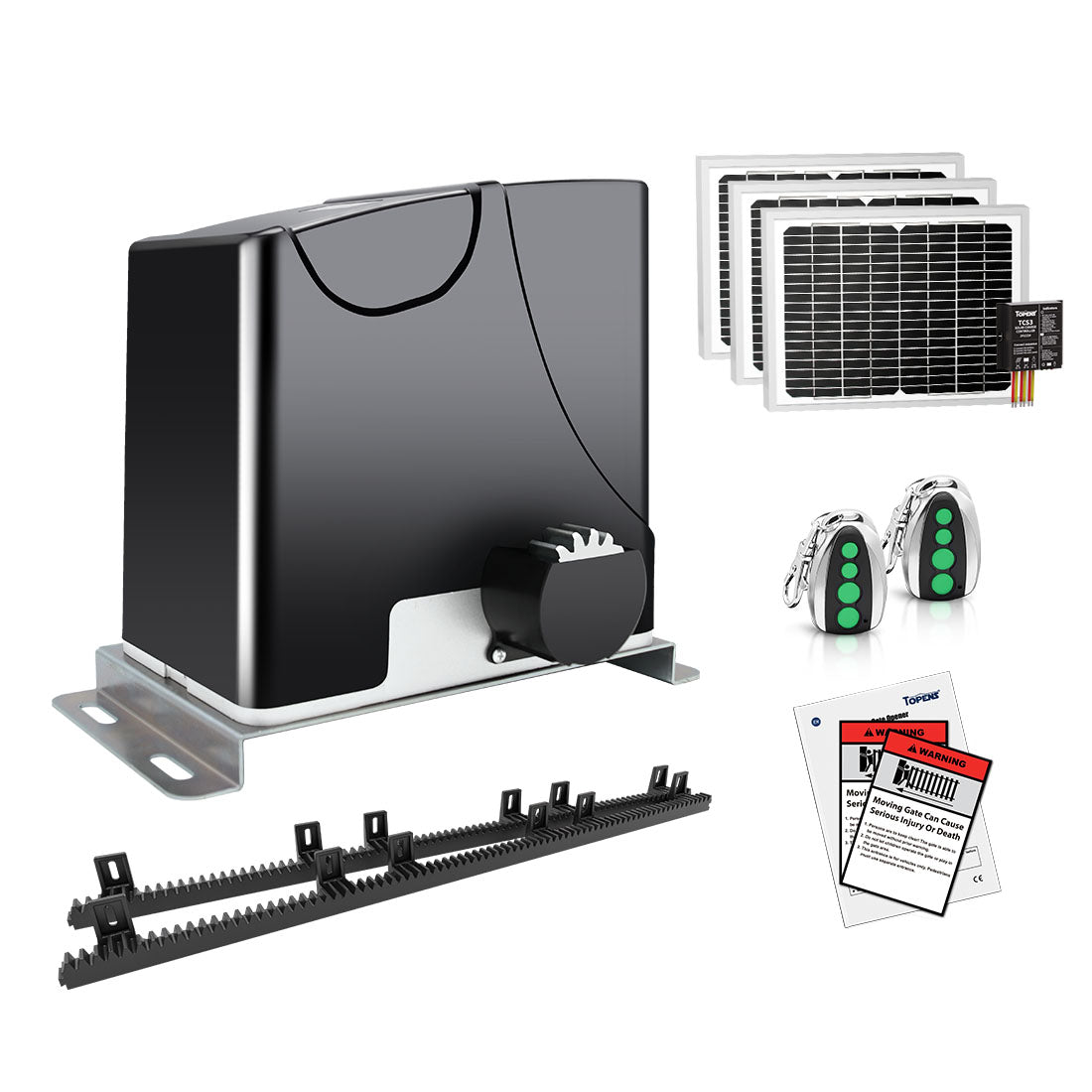
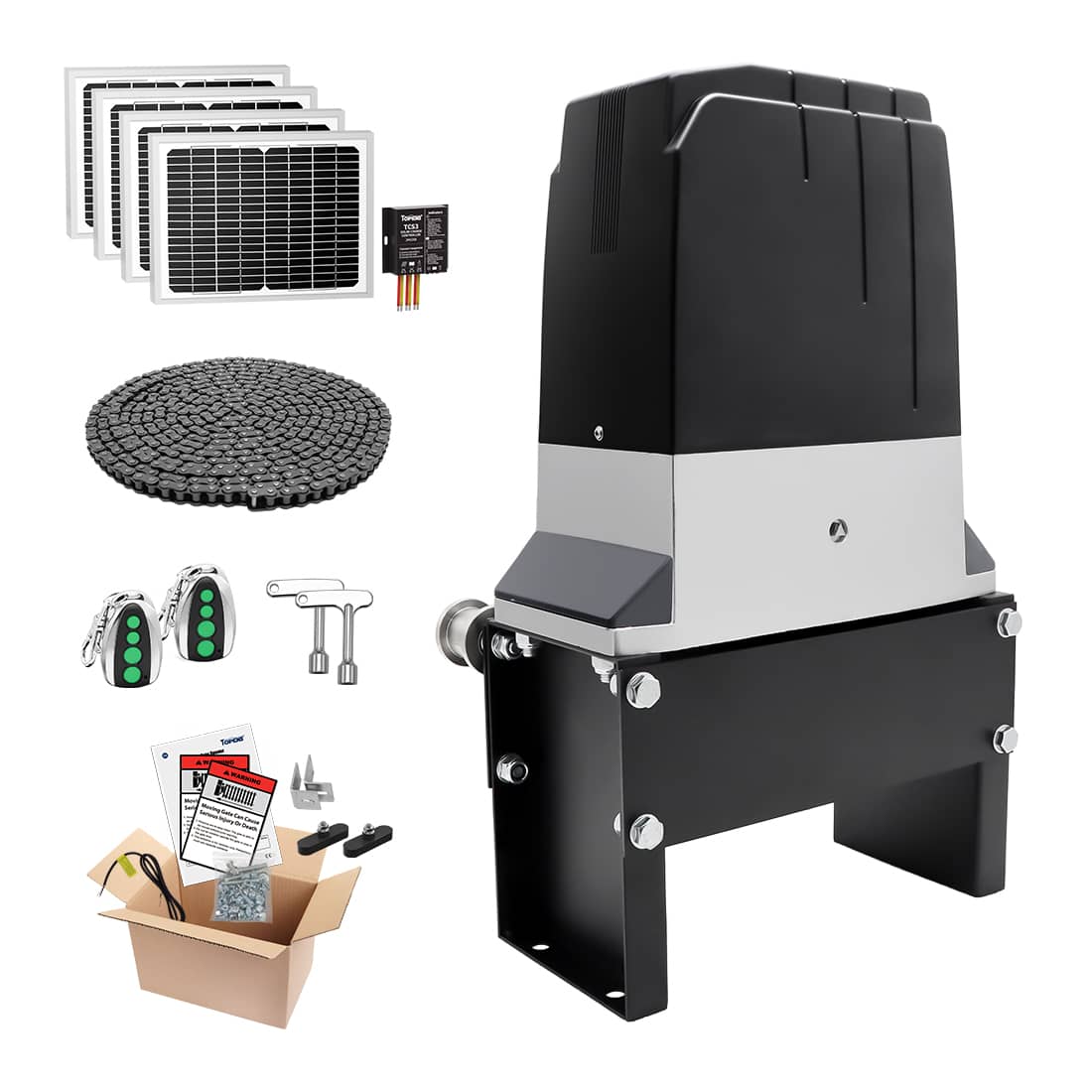
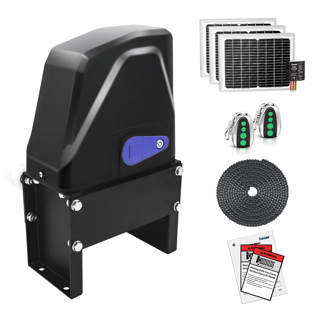
Sliding Gate Openers
| Model | Terminals | Connection Type |
| DKR500ST, DKR1100ST, DKC500S, DKC1100S, DK1000S | OPSW | Direct |
| RK990T, RK1200T, RK2500T, CK1200, CK2500, CK2600 | XB2 + XB1 | Adapter board required |
| RK500T, RK700T, RK1100T, CK700, CK1100, BK800, CF800, LC1100 | OPSW + COM | Direct |
| DKC2000S | LOOP + COM | Direct |
3. Operation Behavior
(1) Emergency Gate Activation
When the Knox switch is activated, the NO and COM contacts close (momentarily or continuously, depending on switch type). The TOPENS control board recognizes this as an open command, and the gate opens immediately to allow emergency access.
(2) Keeping the Gate Open (Optional)
Models XD852(S), XD552(S), XD851(S), XD551(S):
When the Knox switch is turned ON, regardless of whether the switch is maintained or momentary, the gate opens and remains open automatically for emergency access.
All Other Models:
If the gate is equipped with an auto close function and must remain open during extended emergency operations, additional configuration may be required based on the type of Knox switch installed.
A. Maintained Knox Switch
- Turning the switch ON opens the gate.
- The gate remains open until the switch is manually returned to its normal position.
- This method is widely used and accepted where permitted by local fire and building codes.
B. Momentary Knox Switch
If a momentary Knox switch is installed and the gate must remain open, an additional toggle switch is required.
- Connect the toggle switch to the photocell sensor terminals on the control board and enable the photocell sensor function. Please refer to the applicable TOPENS user manual for detail wiring instructions.
- When the toggle switch is turned ON, the auto close function is disabled and the gate remains open.
- When the toggle switch is turned OFF, normal auto close function is restored.
- Clear instructions must be installed inside the Knox Box, such as: “Turn ON this switch to keep the gate open.”
- Clearly labeled ON / OFF markings on the toggle switch are strongly recommended.
You may also refer to the article “How to Keep Your Gate Open with Auto-Close Function Enabled” for additional solutions.
4. Safety, Compliance, and Installation Notes
- Confirm that the Knox switch provides a Normally Open (NO) dry contact before installation.
- If auto close is intentionally disabled for emergency use, clear operating instructions must be placed inside the Knox Box.
- Knox switches are not supplied by TOPENS and must be sourced from qualified third-party suppliers (e.g., Knox).
- Installation must comply with all applicable local AHJ, fire department, and building code requirements.
Proper integration of a Knox Gate & Key Switch with TOPENS gate openers ensures reliable emergency access while maintaining safe and compliant gate operation. By selecting the correct NO dry contact Knox device, following model-specific wiring requirements, and configuring gate behavior in accordance with local codes, you can achieve a professional, code-compliant emergency access solution.
If there is any uncertainty regarding compatibility, wiring terminals, or operational configuration for a specific TOPENS gate opener model, contact TOPENS Technical Support before installation to avoid system damage and ensure full compliance with emergency access requirements.