A circuit breaker is a critical safety component in any TOPENS gate opener system. It protects equipment, wiring, and users by automatically disconnecting the power supply in the event of electrical faults. Proper selection and installation are essential to ensure safe, reliable, and long-term operation.
This guide will help you:
- Understand how circuit breakers work
- Select the appropriate type and rating
- Install and wire the breaker correctly
- Troubleshoot common issues
1. What Is a Circuit Breaker
A circuit breaker is an automatic protective device that disconnects the power supply when it detects:
- Overload (excessive current)
- Short circuit (fault caused by wiring or unintended contact)
This protection helps prevent equipment damage and reduces the risk of fire.
Circuit Breaker vs. Surge Protector
Circuit Breaker: Disconnects power when current exceeds safe limits
Surge Protector: Diverts transient overvoltage (e.g., lightning) to ground
For optimal protection, both devices should be used where applicable.
2. Why Your Gate Opener Needs a Circuit Breaker
The use of a circuit breaker is strongly recommended for all TOPENS gate opener systems.
1) Overload Protection
If the motor encounters abnormal resistance (e.g., obstruction, misalignment, or wear), the current may increase significantly. The breaker will trip to prevent damage.
2) Short Circuit Protection
Faults caused by damaged wiring, incorrect connections, or moisture ingress may result in short circuits. The breaker disconnects power immediately to protect the control board and wiring.
3) Safe Maintenance
A circuit breaker provides a convenient means of safely isolating the power supply during installation, inspection, or maintenance.
3. Types of Circuit Breakers
3.1 By Power Type
AC Circuit Breaker
- Used for mains power (110-120VAC / 220-240VAC)
- Suitable for standard AC-powered gate openers
DC Circuit Breaker
- Used for battery or solar-powered systems
- Designed specifically for direct current applications
Note: An AC circuit breaker must not be used in a DC system.
3.2 By Pole Configuration
1P (Single Pole)
- Disconnects the live (L) conductor only
- Suitable for basic or low-risk applications
1P+N (Single Pole + Neutral)
- Disconnects both live (L) and neutral (N) conductors
- Overcurrent protection is typically provided on the live conductor
- Recommended for most residential installations
2P (Double Pole)
- Disconnects both conductors simultaneously
- Provides full isolation
- Suitable for main supply isolation and enhanced safety
3.3 By Function
Standard Circuit Breaker
- Provides protection against overload and short circuit
Residual Current Device (RCD / RCBO)
- Detects residual (leakage) current and reduces the risk of electric shock
- Available in 1P+N or 2P configurations
- Recommended for outdoor installations
4. How to Choose the Right Circuit Breaker
4.1 General Selection Guidelines
For AC-Powered Gate Openers
- Use a 1P+N or 2P AC circuit breaker compliant with applicable standards
- Where residual current protection is required, use an RCD or RCBO
- Select a rated current approximately 1.5 × the rated current of the gate opener
- Avoid oversizing the breaker, as this may reduce protection effectiveness
For Battery / Solar-Powered Systems
- Use a dedicated 2--pole DC circuit breaker for isolation and overcurrent protection
- Ensure the rated voltage is equal to or higher than the system voltage
- Select a breaker with trip characteristics suitable for motor loads (e.g., thermal-magnetic type)
- If leakage protection is required, use a dedicated DC residual current device
Notes:
- Battery-powered systems are typically protected by fuses; however, for lithium battery systems, using a DC circuit breaker is recommended to improve protection.
- For hybrid systems (AC + battery), install an AC breaker on the AC side and a DC breaker on the battery side.
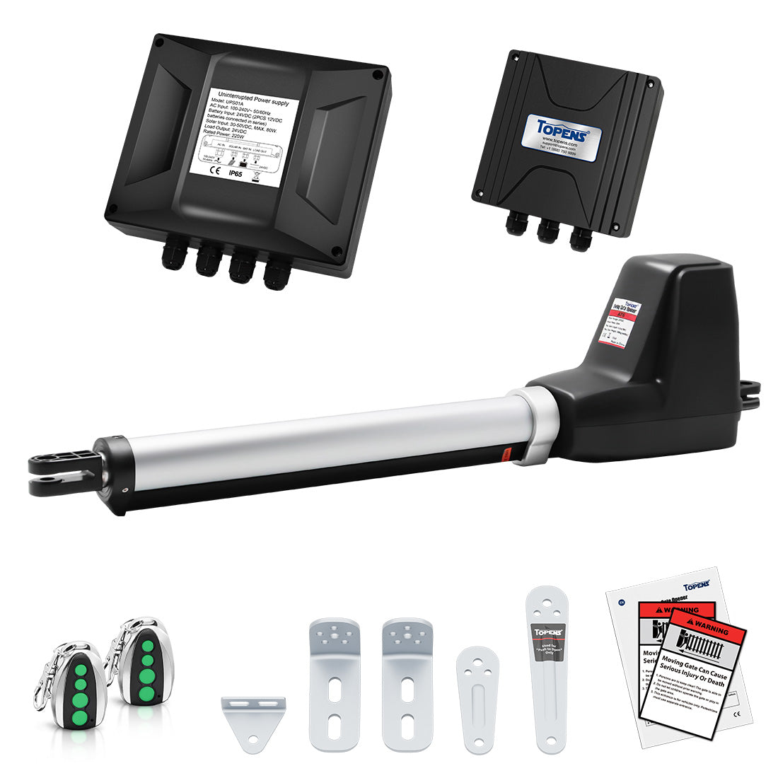
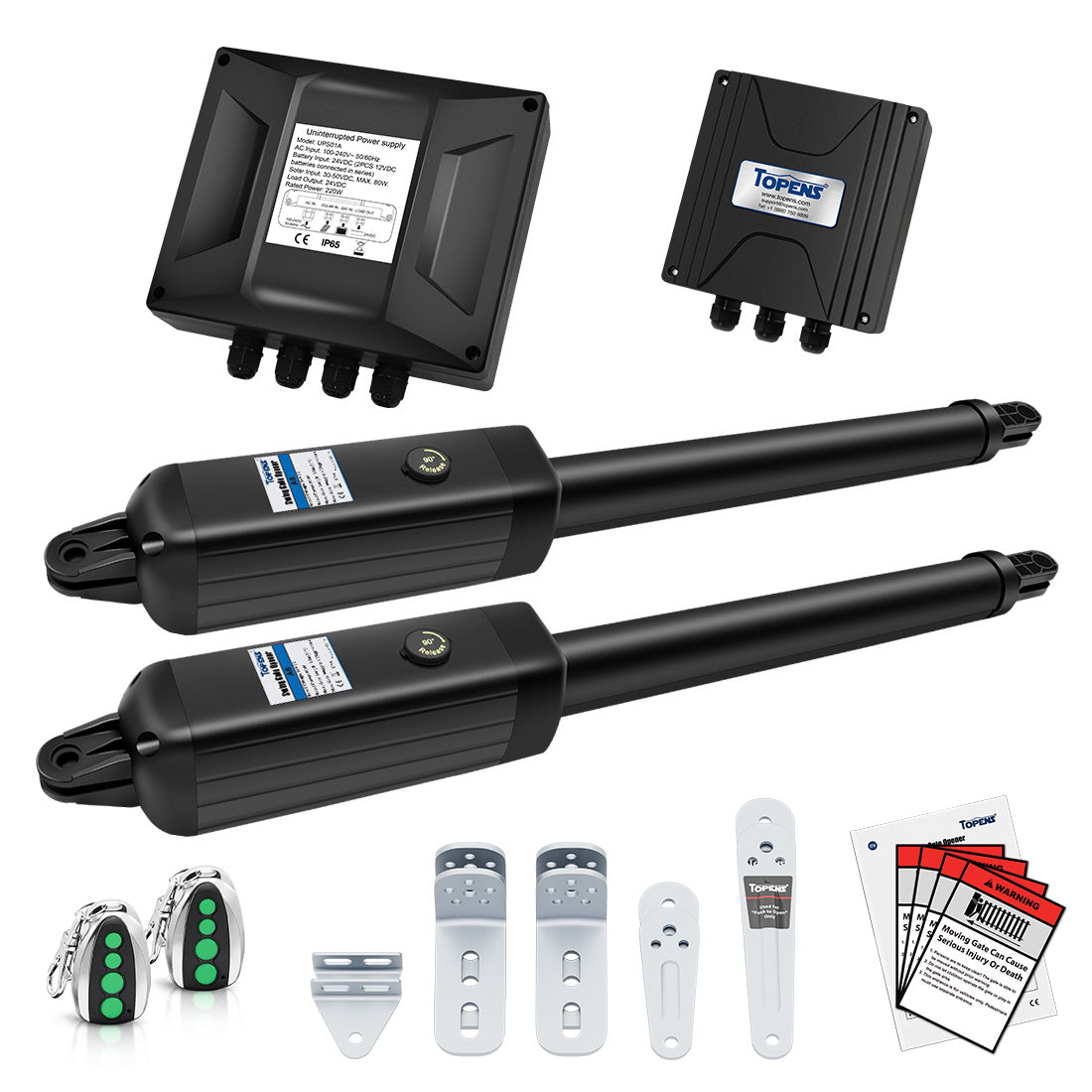
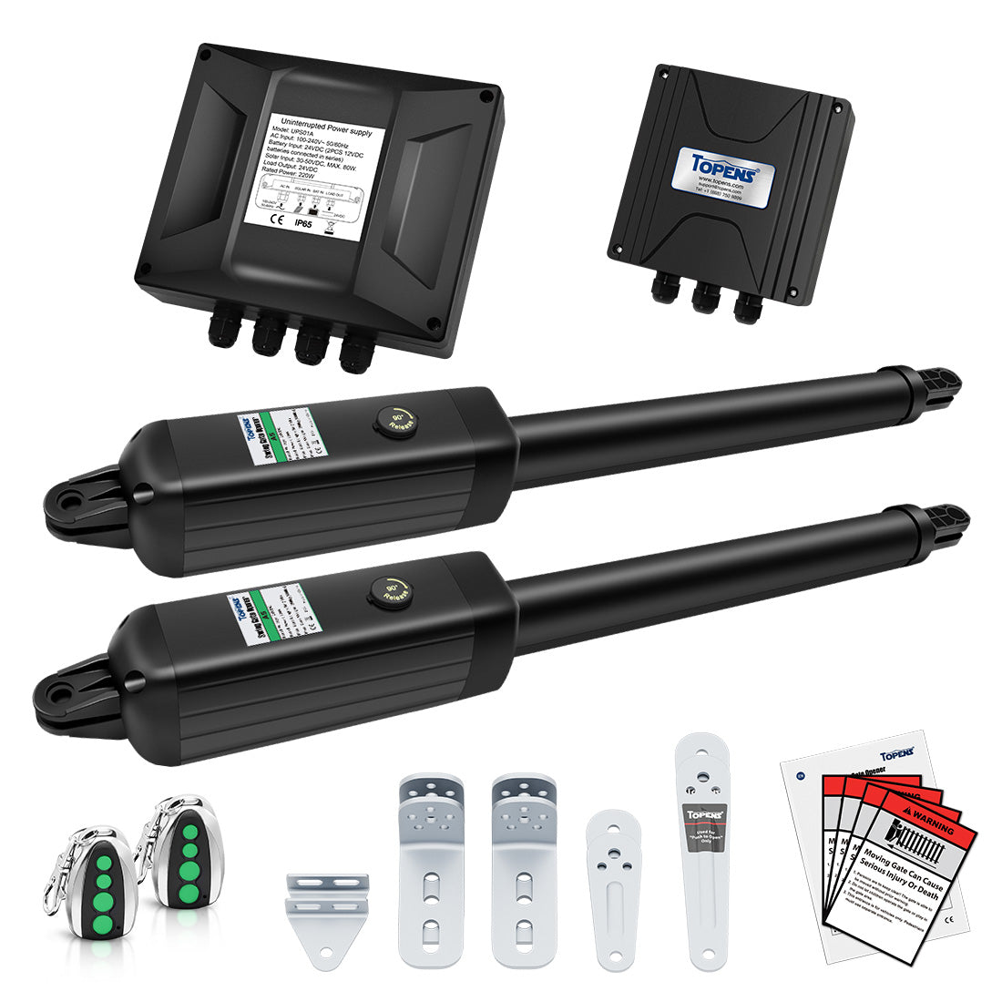
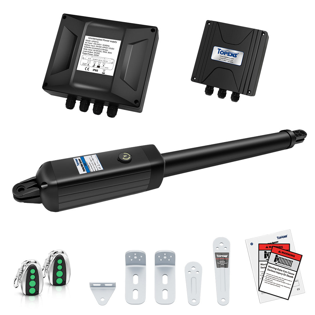
4.2 Recommended Breaker Ratings by Model
The tables below provide recommended circuit breaker ratings for each model under different power supply configurations, assuming no accessories are connected.
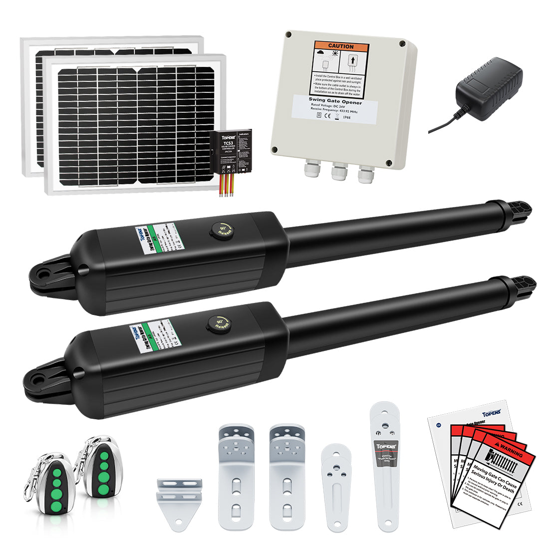
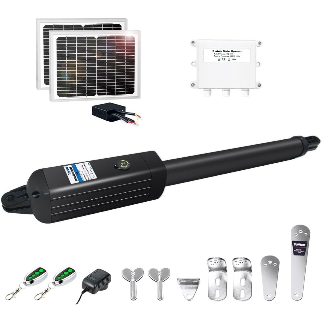
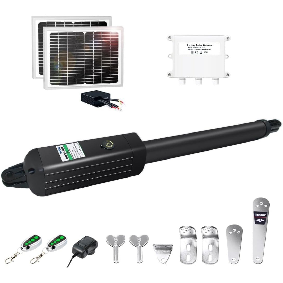
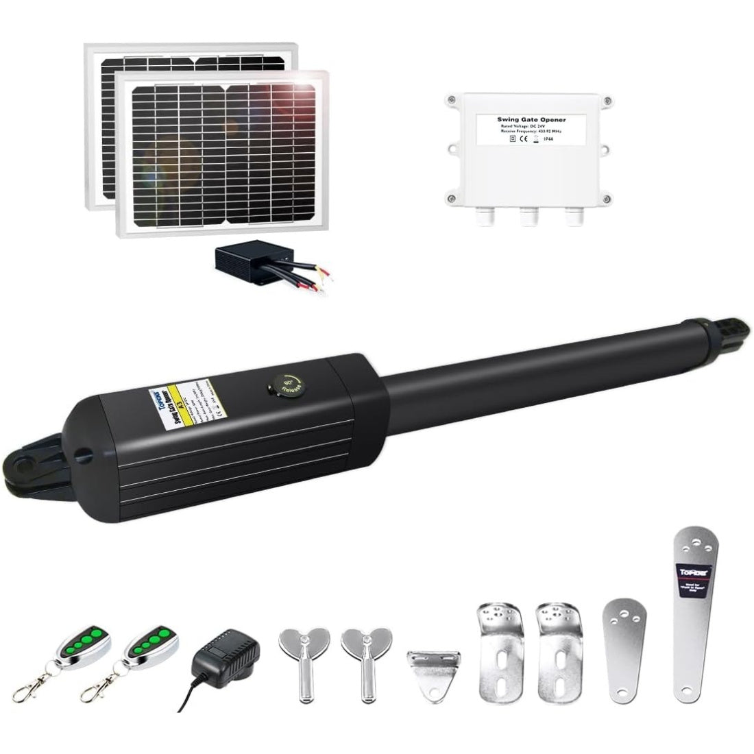
Swing Gate Openers
| Model | 110–120VAC | 220–240VAC | 24VDC Battery |
| A3S |
1A~2A |
1A |
3A~4A |
| PW302 / KD702 |
2A~3A |
1A~2A |
4A~6A |
| A5S / A5131 / AT6131(S) / XD551(S) |
2A~3A |
1A~2A |
4A~6A |
| AD5S / PW502 / A5132 / AT6132S / XD552(S) / AT602 |
3A~4A |
2A~3A |
6A~8A |
| A8(S) / A8131 / AT12131(S) / XD851(S) |
2A~3A |
1A~2A |
5A~7A |
| AD8S / PW802 / A8132 / AT12132S / XD852(S) / AT1202 |
3A~4A |
2A~3A |
8A~10A |
| JY9132 |
3A~5A |
2A~3A |
10A~15A |
Sliding Gate Openers (DC Models)
|
Model |
110–120VAC |
24VDC Battery |
| DKR500ST / DKC500S |
4A~7A |
10A~15A |
| DK1000S |
5A~7A |
17A~22A |
| DKR1100ST / DKC1100S |
6A~8A |
20A~25A |
| DKC2000S |
7A~10A |
25A~30A |
| DLC2000S |
6A~8A |
20A~25A |
Sliding Gate Openers (AC Models)
|
Model |
110–120VAC |
220–240VAC |
| RK500T / RK700T / CK700 |
4A~6A |
3A~5A |
| RK990T / BK800 |
5A~7A |
3A~5A |
| RK1100T / CK1100 / CF800 |
6A~8A |
4A~6A |
| RK1200T / CK1200 / LC1100 |
7A~9A |
4A~7A |
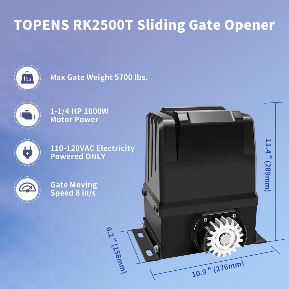
| RK2500T / CK2500 / CK2600 |
11A~13A |
7A~9A |
Garage Door Openers
|
Model |
110–120VAC |
220–240VAC |
| CASAR800 |
— |
1A~2A |
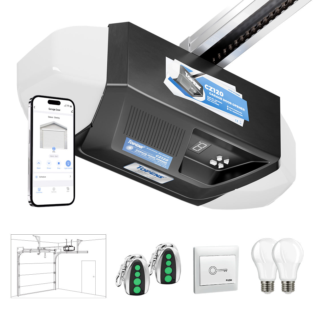
| CZ120 |
2A~3A |
— |
5. Installation and Wiring
5.1 Typical System Layout
AC System:
AC Power → AC Circuit Breaker → Power Supply / Adapter → Control Board
DC System:
Battery → DC Circuit Breaker → Control Board
5.2 AC Breaker Wiring
Install the breaker upstream of the power supply / adapter, as close to the power supply as possible.
1) 2P Breaker with Residual Current Protection (Recommended)
- Top terminals (input): Left – Live (L), Right – Neutral (N)
- Bottom terminals (output): Left – Live (L), Right – Neutral (N)
2) 1P+N Breaker with Residual Current Protection
- Top terminals (input): L – Live (L), N – Neutral (N)
- Bottom terminals (output): L – Live (L), N – Neutral (N)
- The neutral conductor must be connected to the “N” terminal; do not reverse connections
Important: Do not share the neutral conductor with other circuits on the load side, as this may cause unintended tripping.

5.3 DC Breaker Wiring
Install the breaker between the battery and the control board, as close to the battery as possible.
- Top terminals (input): Left – Positive (+DC) , Right – Negative (-DC)
- Bottom terminals (output): Left – Positive (+DC), Right – Negative (-DC)
Notes:
- Polarity must be strictly observed; reversed connections may damage the breaker or system.
- Do not replace a DC breaker with an AC breaker.

6. Troubleshooting: Breaker Keeps Tripping
If the circuit breaker trips frequently, follow the steps below:
Step 1: Verify Breaker Rating
- Turn off the power before inspection
- Ensure that the breaker rating is appropriate (approximately 1.5 × rated current)
An undersized breaker may trip during normal operation, while an oversized breaker may reduce protection effectiveness.
Step 2: Check for Wiring Issues
- Inspect wiring for damage, loose connections, or short circuits
- Check for insulation failure or moisture ingress
- Do not operate the system until faults are corrected
Step 3: Check Gate Movement
- Release the clutch and move the gate manually
- Ensure smooth operation; if not, check for obstruction, misalignment and installation issues
Mechanical resistance may cause motor overload and breaker tripping.
Step 4: Test Control Board
- Keep the clutch released
- Disconnect the motor wires and all wired accessories from the control board
- Turn on the power and operate the system using the remote control
- If the breaker trips, the control board may be faulty
Step 5: Test the Motor
- If the breaker does not trip in Step 4, reconnect the motor wires only
- Try operating the system again
- If the breaker trips, the motor is likely faulty
Step 6: Check Accessories
- Reconnect accessories one at a time and test the system after each connection
- If tripping occurs after connecting a device, that device or its wiring may be faulty
By selecting an appropriate circuit breaker and following proper installation and troubleshooting procedures, the system can be effectively protected against electrical faults, improving safety and extending service life.