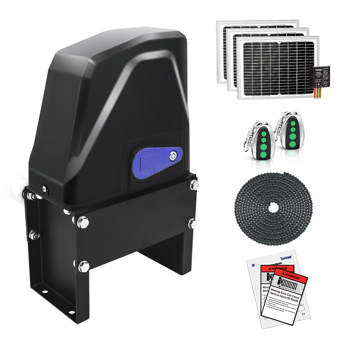
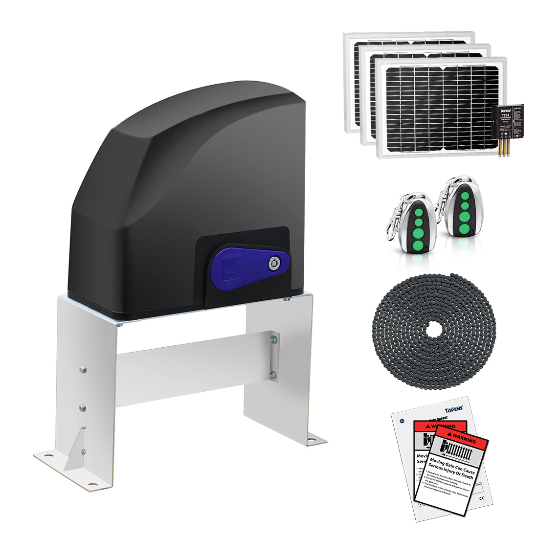
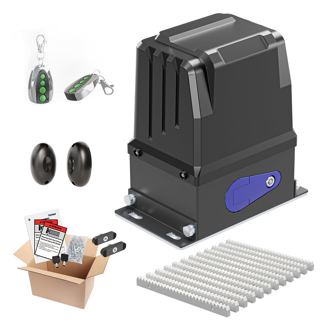
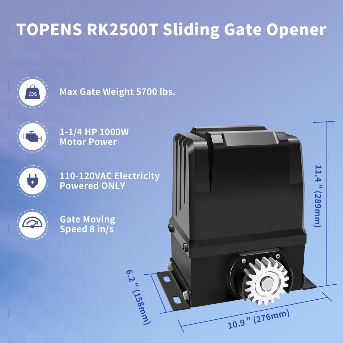
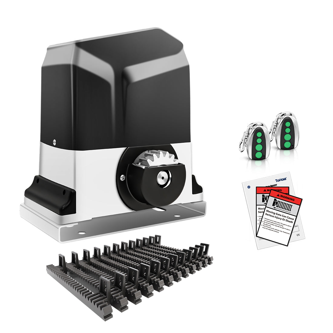
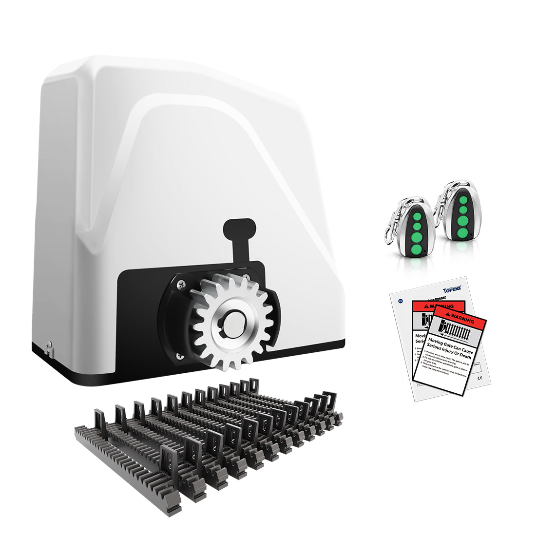
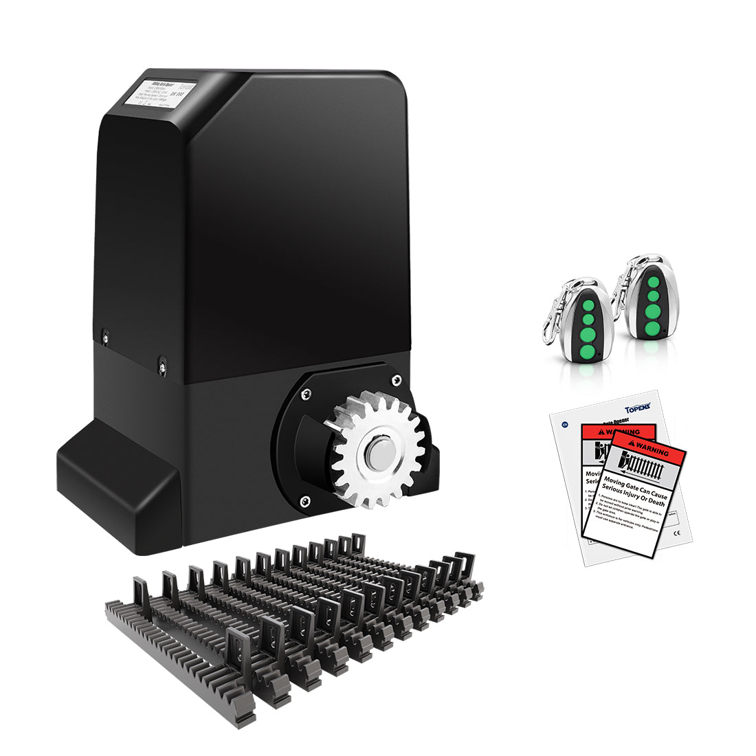
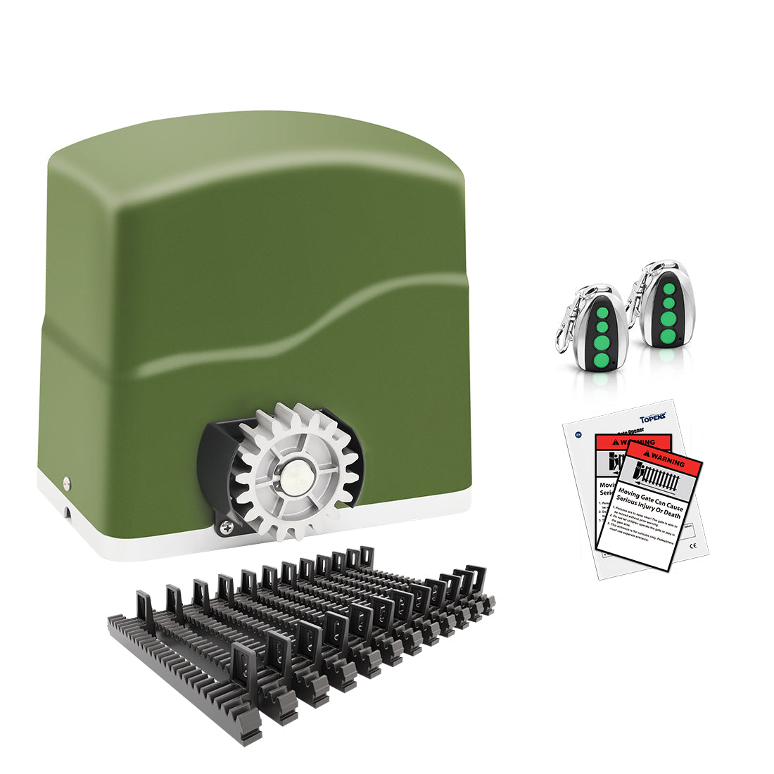
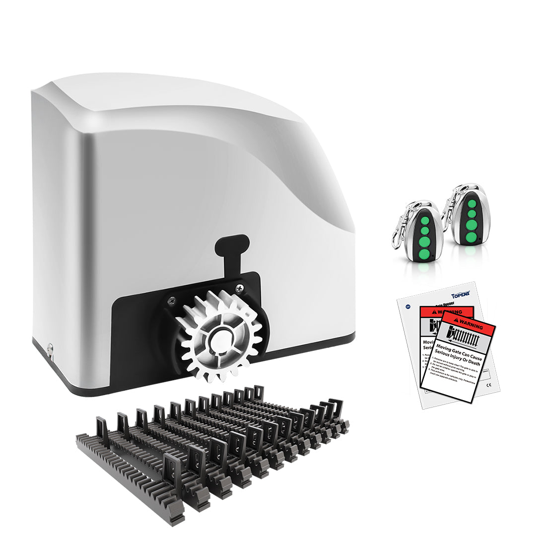
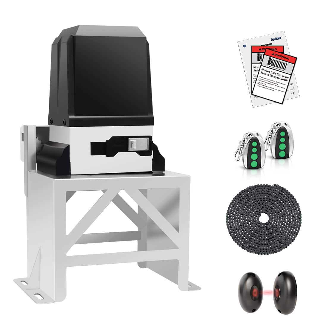
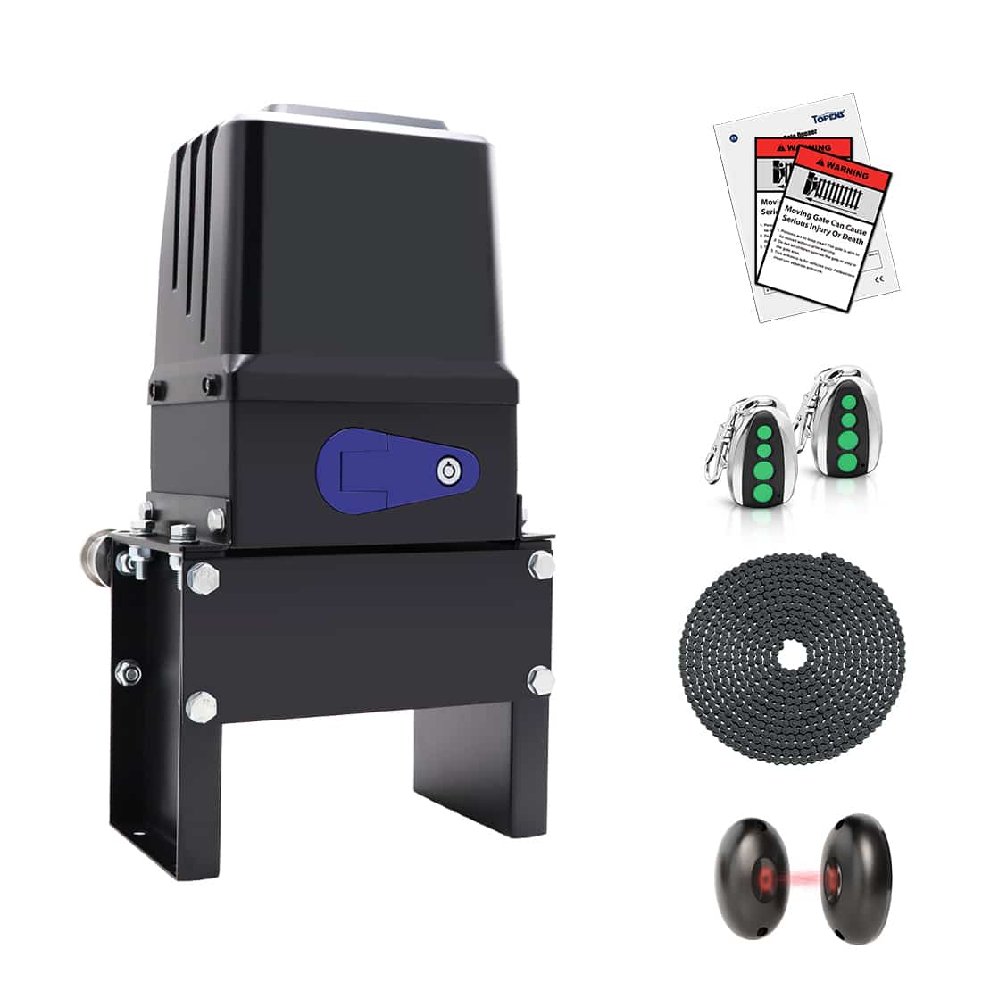
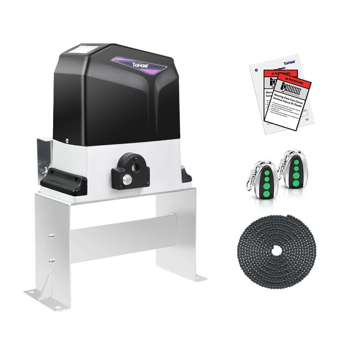
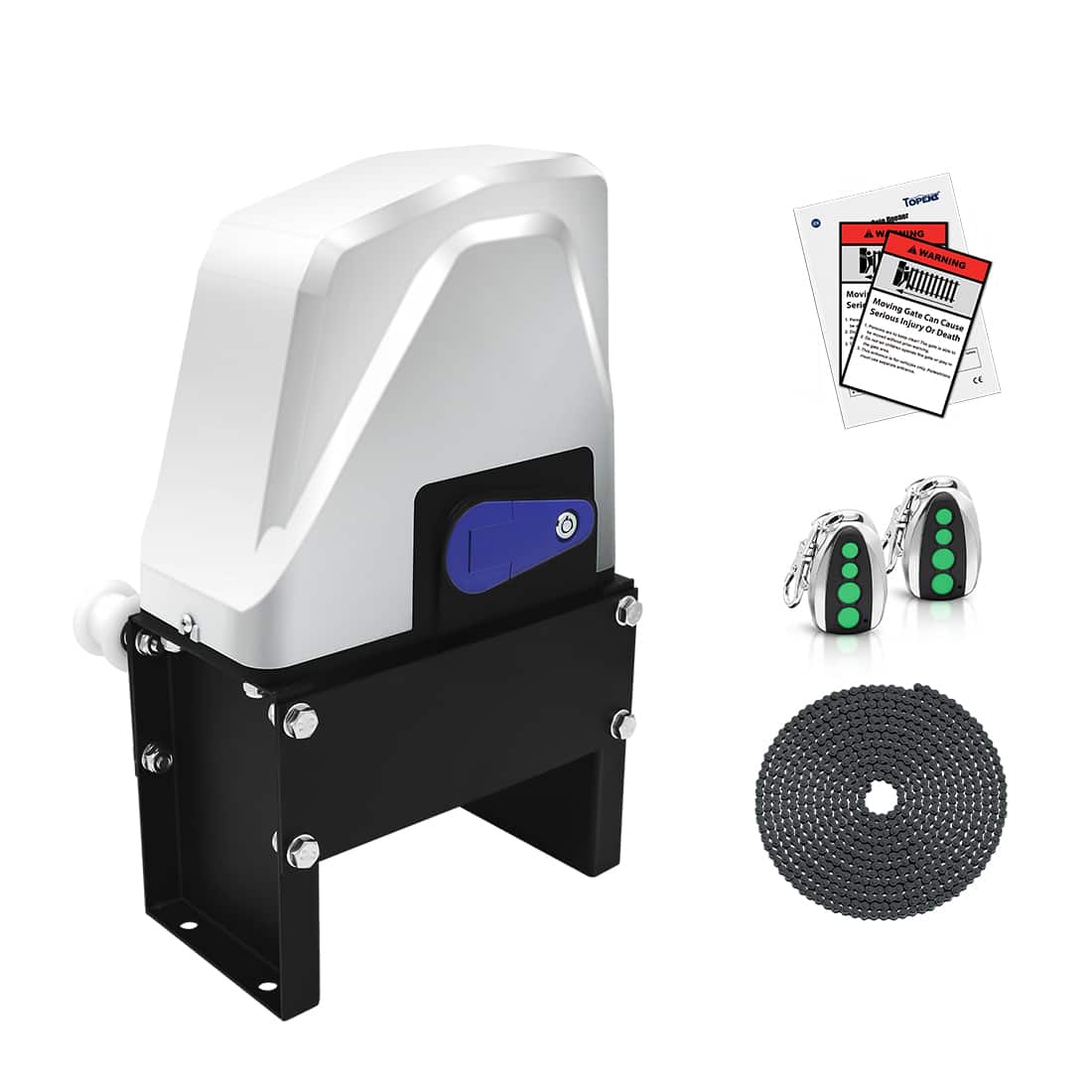
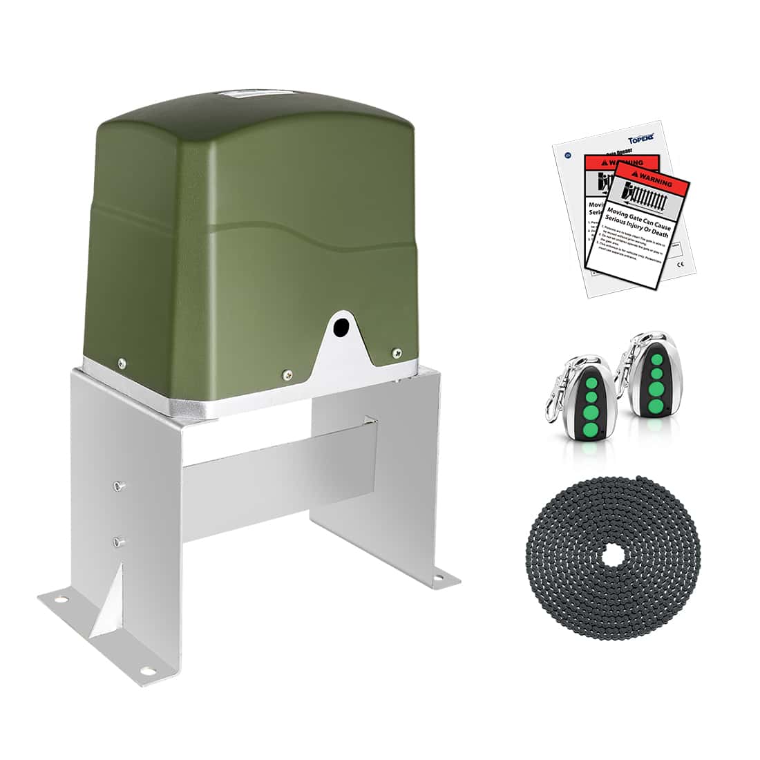
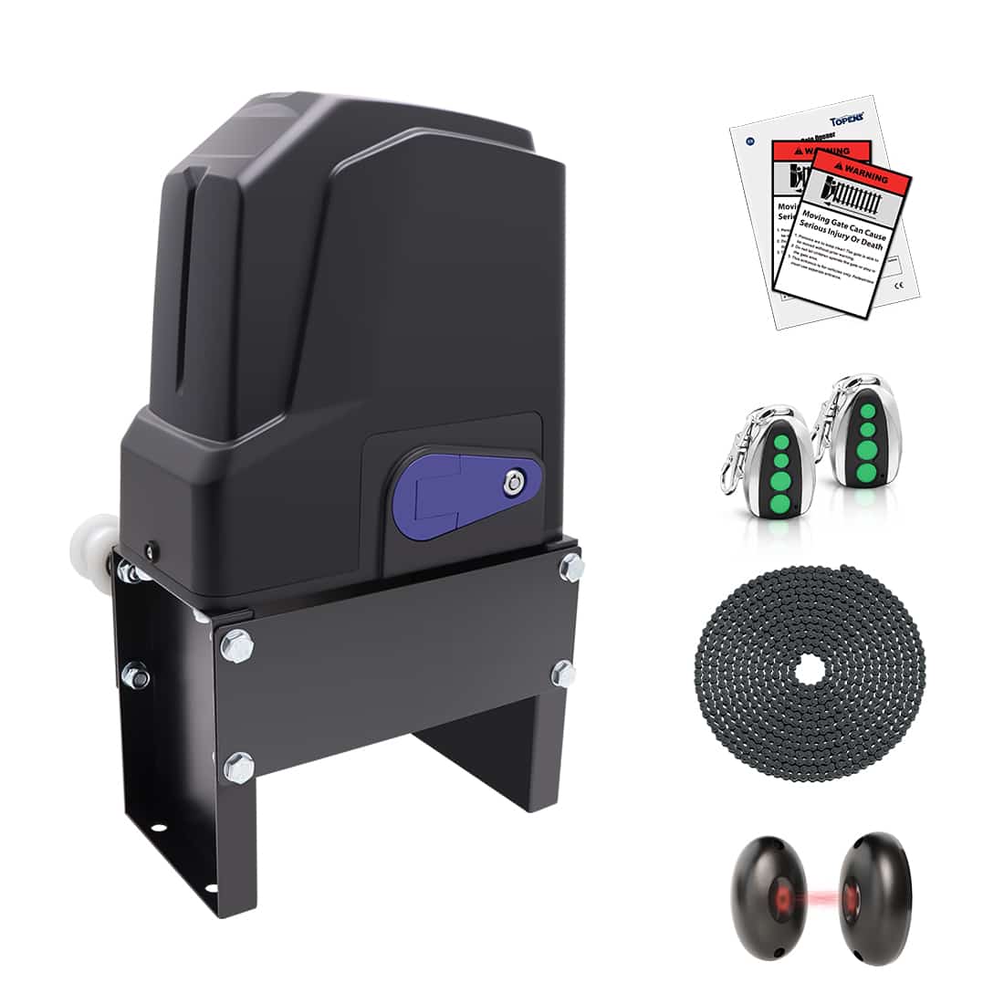
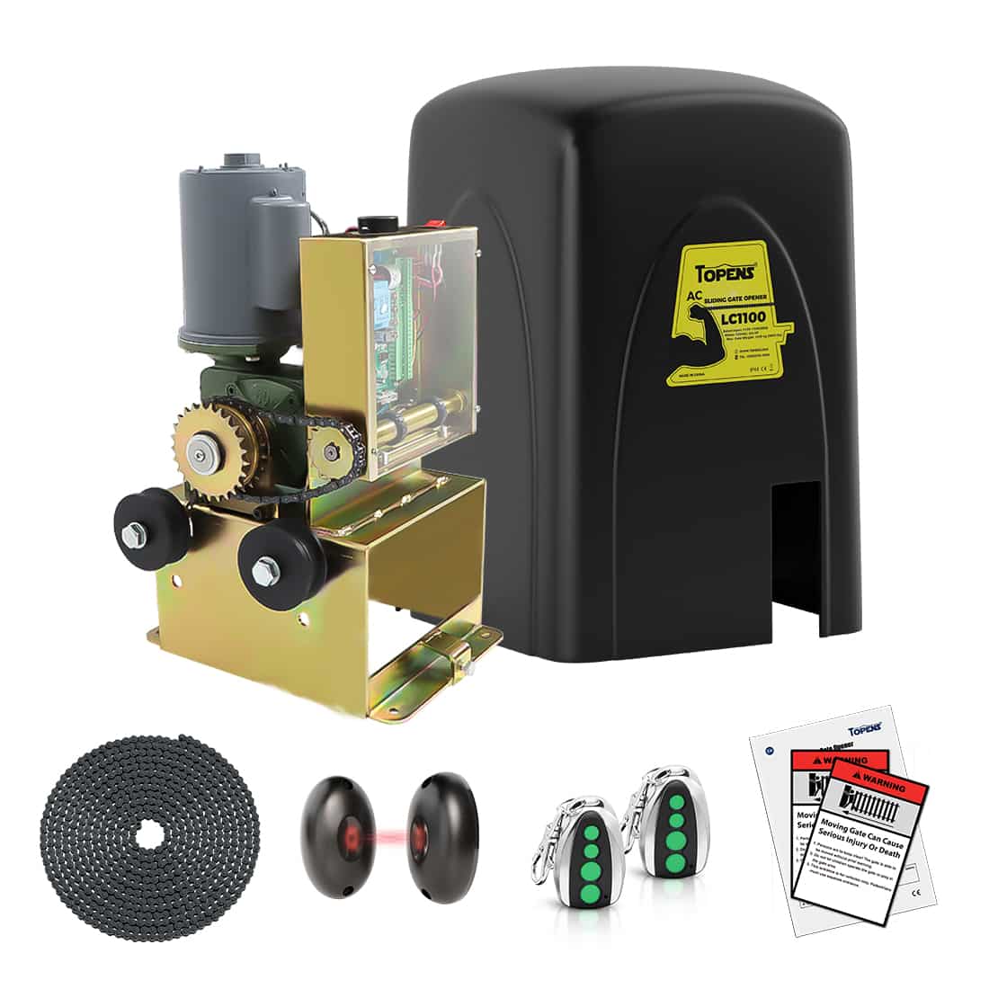
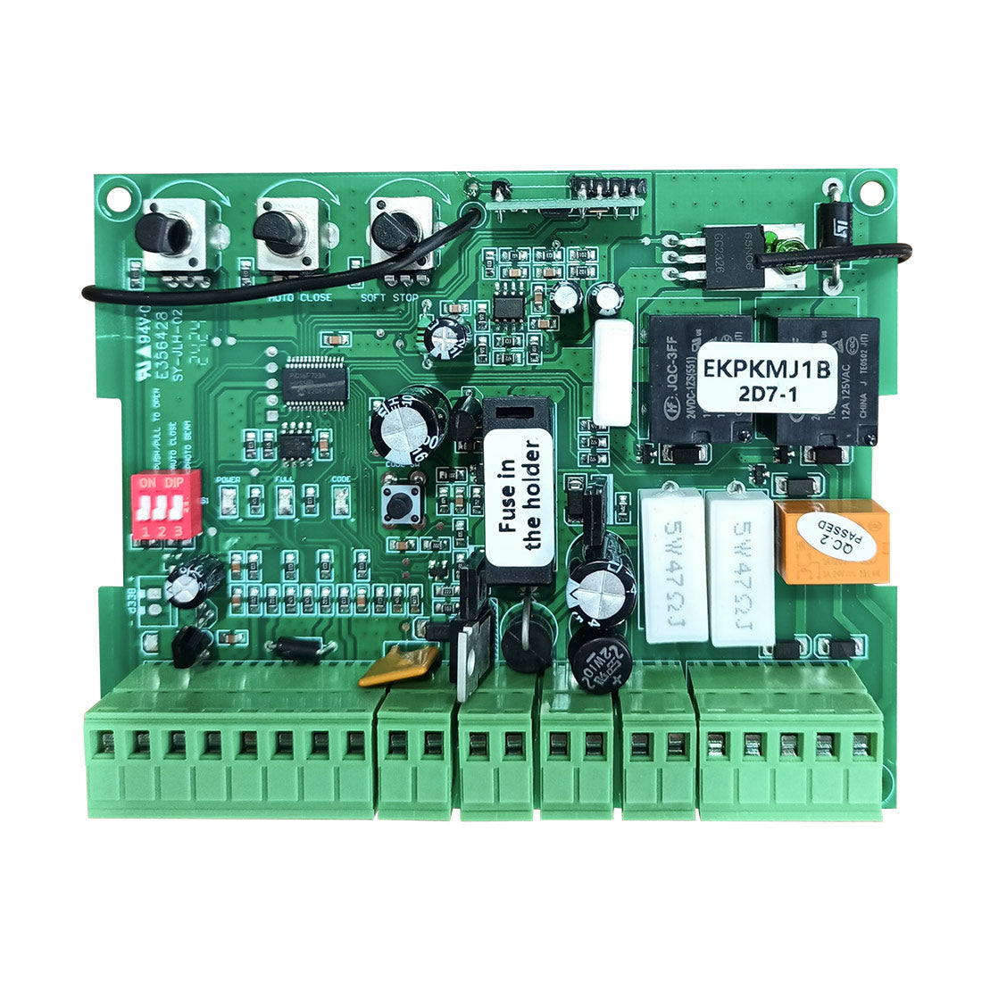
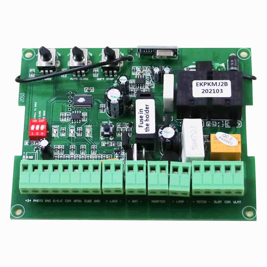
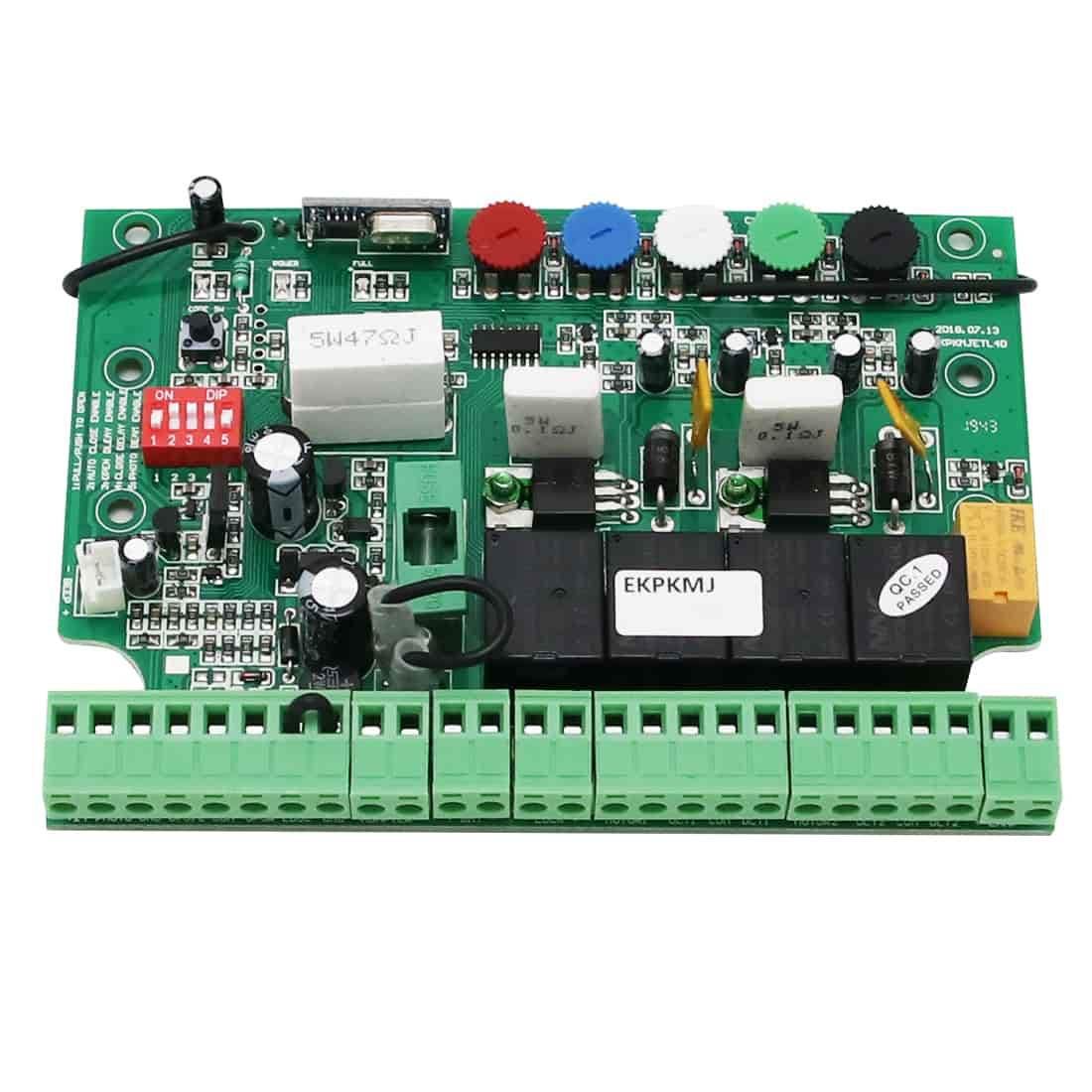
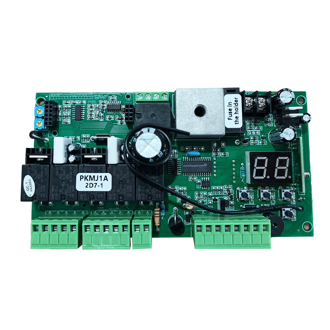
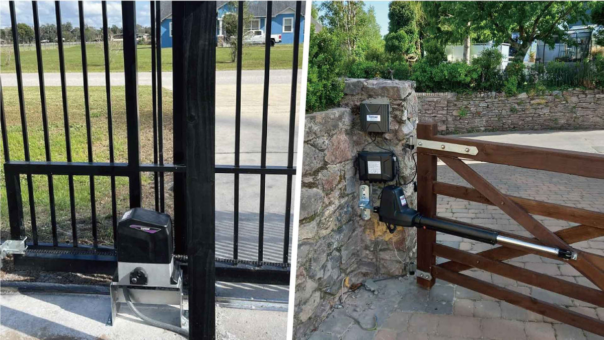
Applicable Models: RK990T, RK1200T, CK1200, RK2500T, CK2500, RK2600T, CK2600, DKC2000S, LC1100
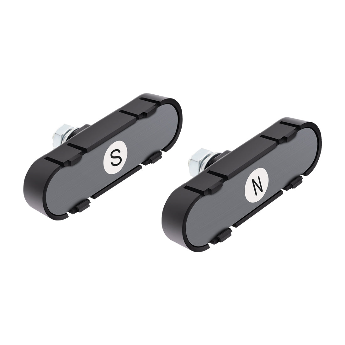
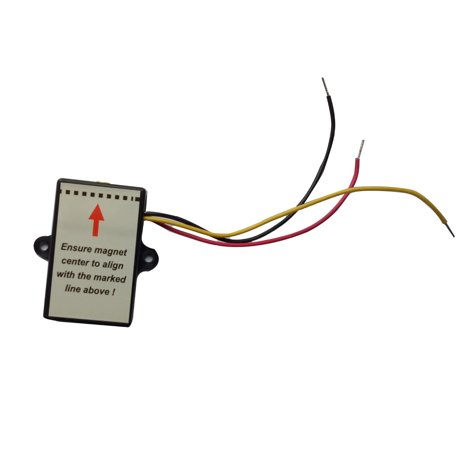
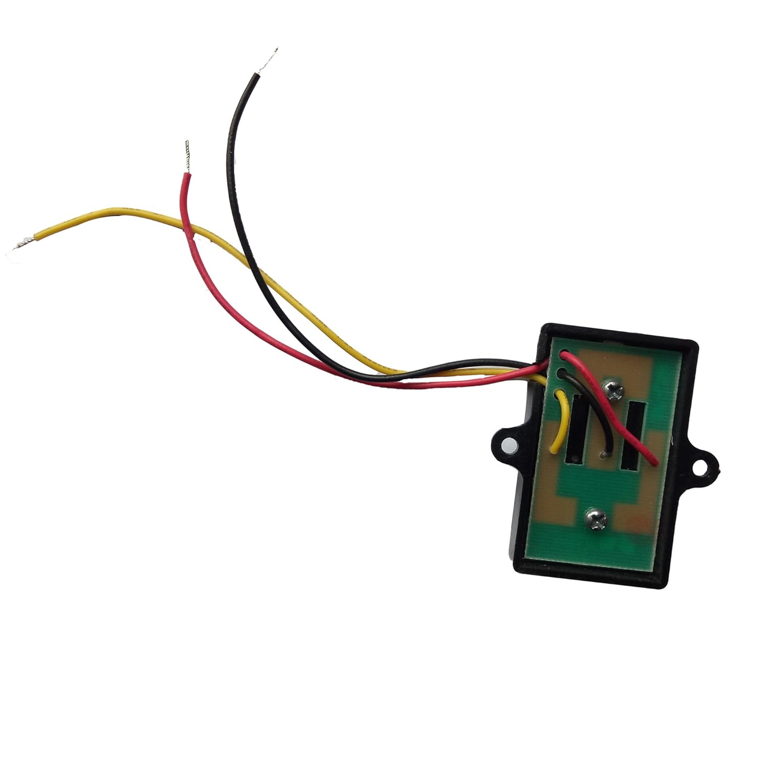
If your TOPENS sliding gate opener continues running after the gate reaches the fully open or fully closed position, the problem is typically related to the limit system. Common causes include incorrectly positioned magnets, a faulty magnetic limit switch, loose or damaged wiring, or a defective control board.
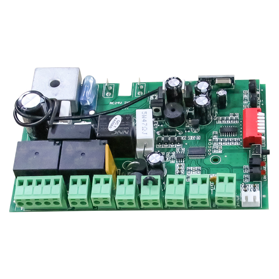
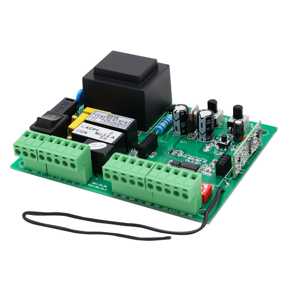
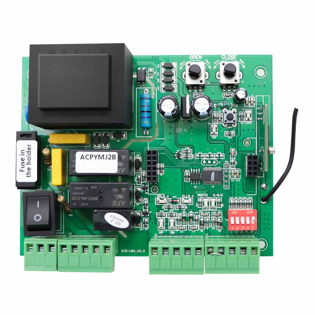
Fortunately, many TOPENS sliding gate opener models are equipped with limit indicator LEDs on the control board. These LEDs simplify troubleshooting by showing whether the opener is correctly detecting the magnets during gate movement.
This guide explains how the limit indicator LEDs function and provides a step-by-step troubleshooting procedure to help you identify the source of the problem quickly and accurately.
1. Understanding TOPENS Limit Indicator LEDs
Different TOPENS sliding gate opener models use different limit-switch logic. Before troubleshooting, it is important to understand how the indicator LEDs are designed to operate on your specific model.
Type 1: Normally Open Limit-Switch Logic
Applicable Models: RK990T, RK1200T, CK1200, RK2600T, CK2600, DKC2000S
LED Behavior:
- When the magnet is not detected, the LED remains OFF.
- When the magnet is detected, the LED turns ON.
Typical Indicator Labels:
- UP / DN (RK990T, RK1200T, CK1200, RK2600T, CK2600)
- HI / LOW (DKC2000S)
Type 2: Normally Closed Limit-Switch Logic
Applicable Models: RK2500T, CK2500, LC1100
LED Behavior:
- When the magnet is not detected, the LED remains ON.
- When the magnet is detected, the LED turns OFF.
Typical Indicator Labels:
- UP / DN (RK2500T, CK2500)
Note: The LC1100 control board includes limit indicator LEDs, but these LEDs are not labeled.
Quick Reference
| Limit-Switch Logic | Applicable Models | Indicator LEDs | LED Behavior | |
| Magnet Not Detected | Magnet Detected | |||
| Normally-Open (NO) | RK990T, RK1200T, CK1200, RK2600T, CK2600 | UP / DN | OFF | ON |
| DKC2000S | HI / LOW | OFF | ON | |
| Normally-Closed (NO) | RK2500T, CK2500 | UP / DN | ON | OFF |
| LC1100 | Unlabled | ON | OFF | |

2. Step-by-Step Troubleshooting Procedure
For Normally Open Models (RK990T, RK1200T, CK1200, RK2600T, CK2600, DKC2000S)
1. Disengage the clutch.
2. Use the remote control to active the motor.
3. Manually push the gate toward the open position until the magnet passes the limit switch.
4. Observe the corresponding limit indicator LED on the control board.
- If the LED turns ON but the motor keeps running, the limit switch is correctly detecting the magnet, and the issue is most likely related to the control board.
- If the LED does not respond, the control board is not receiving the limit signal. Possible causes include: incorrect magnet installation or alignment, a defective limit switch, or loose or damaged wiring. In this case, verify the magnet position and alignment, inspect the limit switch, and ensure that all wiring connections are secure and undamaged.
5. Press the remote control again to run the motor in the opposite direction.
6. Repeat the same procedure for the closed limit position and observe the corresponding LED.
For Normally Closed Models (RK2500T, CK2500, LC1100)
Follow the same testing procedure described above and observe the corresponding limit indicator LED.
- If the LED turns OFF but the motor keeps running, the limit switch is working correctly, and the control board is likely defective.
- If the LED remains ON, the control board is not receiving the limit signal. The problem is typically caused by incorrect magnet positioning, a faulty limit switch, or wiring-related issues.
Special Note for LC1100
On the LC1100 model, disengaging the clutch cuts power to the system. As a result, the indicator LEDs cannot be observed while manually moving the gate.
To troubleshoot this model:
1. Keep the clutch engaged and use the remote control to open the gate while observing whether the indicator LED responds correctly at the exact moment the magnet passes the limit switch.
2. Press the remote control again to close the gate and observe the corresponding LED response.
3. Why the LED May Flash Instead of Remaining Continuously ON or OFF
Many users expect the limit indicator LED to remain continuously ON or OFF after the gate stops. However, this is not always the case.
As the magnet passes the limit switch, the LED should respond immediately. Even a brief change in LED status confirms that the limit switch has successfully detected the magnet.
In some situations:
- On a normally open model, the LED may flash briefly instead of remaining ON.
- On a normally closed model, the LED may briefly turn OFF and then turn back ON.
This behavior is common when the gate coasts slightly beyond the magnetic sensing area due to motor inertia. It does not indicate a hardware defect.
If the gate travels beyond the desired stopping point, adjust the magnets slightly toward the center of the gate travel path. This allows the opener to detect the magnets earlier and stop the gate more precisely.
If you want the LED status to remain stable after the gate stops, you may install a positive stop at the point where the magnet is detected. This helps ensure the gate stops at the same location during every operating cycle.

4. Final Takeaways
When troubleshooting a TOPENS sliding gate opener that fails to stop at the limit position, always start by checking the limit indicator LEDs if your model features them.
These LEDs provide one of the fastest and most reliable methods for determining whether the problem originates from the limit system or the control board. In many cases, simply adjusting the magnet position resolves the issue without the need to replace any components.
For advanced troubleshooting and technical support, it is highly recommended to record:
- A video of the gate’s movement
- The behavior of the limit indicator LEDs
- The exact moment the gate reaches the limit position
Providing this information can help technicians identify the issue more efficiently and recommend the correct solution.