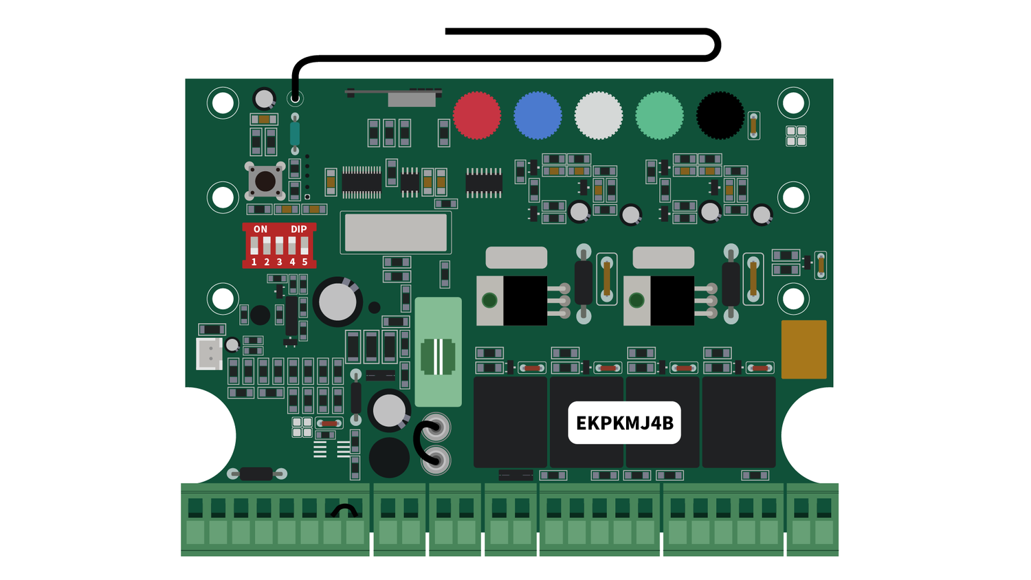
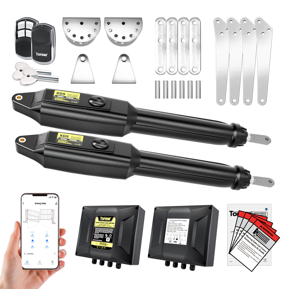
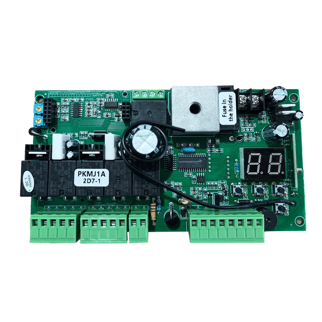
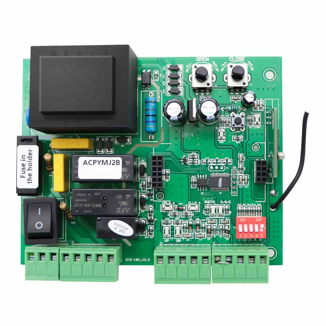
Knowing the roles of wiring terminals on the control board of your gate opener is crucial to avoid misunderstandings or frustration. This article aims to provide insight into the functionality of your TOPENS swing gate opener system, using the EKPKMJ4B control board on TOPENS A5132 as an example.


Note:
Each terminal is not designed to function independently; connecting accessories requires utilizing multiple terminals simultaneously.
Function Descriptions:
Terminal 1 “+24” and Terminal 3 “GND”:
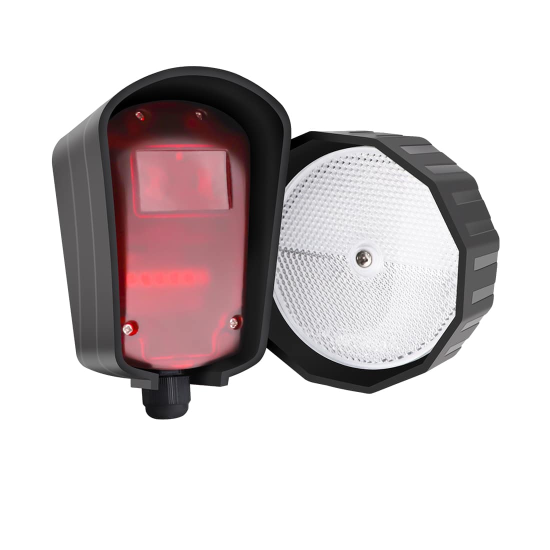
Function: Provide 24VDC voltage output to power photocell beam sensors.
Note: Output is only active during motor operation and the terminals can power a third-party beam sensor.
Terminal 2 “PHOTO” and Terminal 3 “GND”:
Function: Receive signal input from a photocell beam sensor, operating on a normally closed (NC) input basis (NC: normally closed; NO: normally open).
Notes:
- The gate responds based on the sensor status (blocked or unblocked). When the sensor is blocked, the two terminals are open-circuit and the gate will stop or reverse accordingly.
- Connection to a third-party photo sensor with normally closed dry contact signal output is possible.
Terminal 4 “O/S/C” and Terminal 5 “COM”:
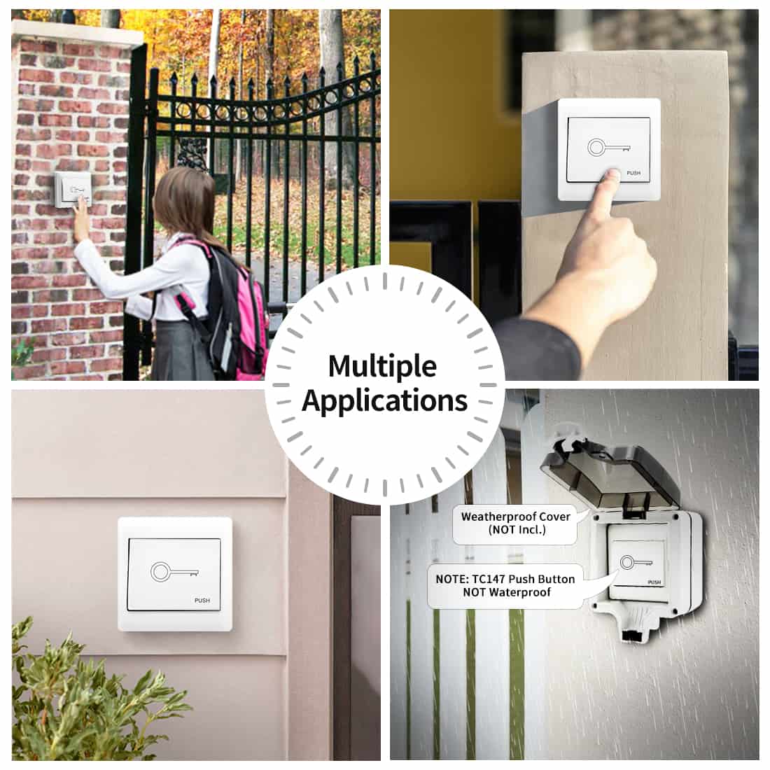
Function: Control gate operation through a normally open dry contact signal input, commonly connected to push button, wired keypad, and external receiver for cyclic gate operation (open/stop/close/stop).
Note: Compatible with third-party push buttons, wired keypads, or external receivers with normally open dry contact signal output.
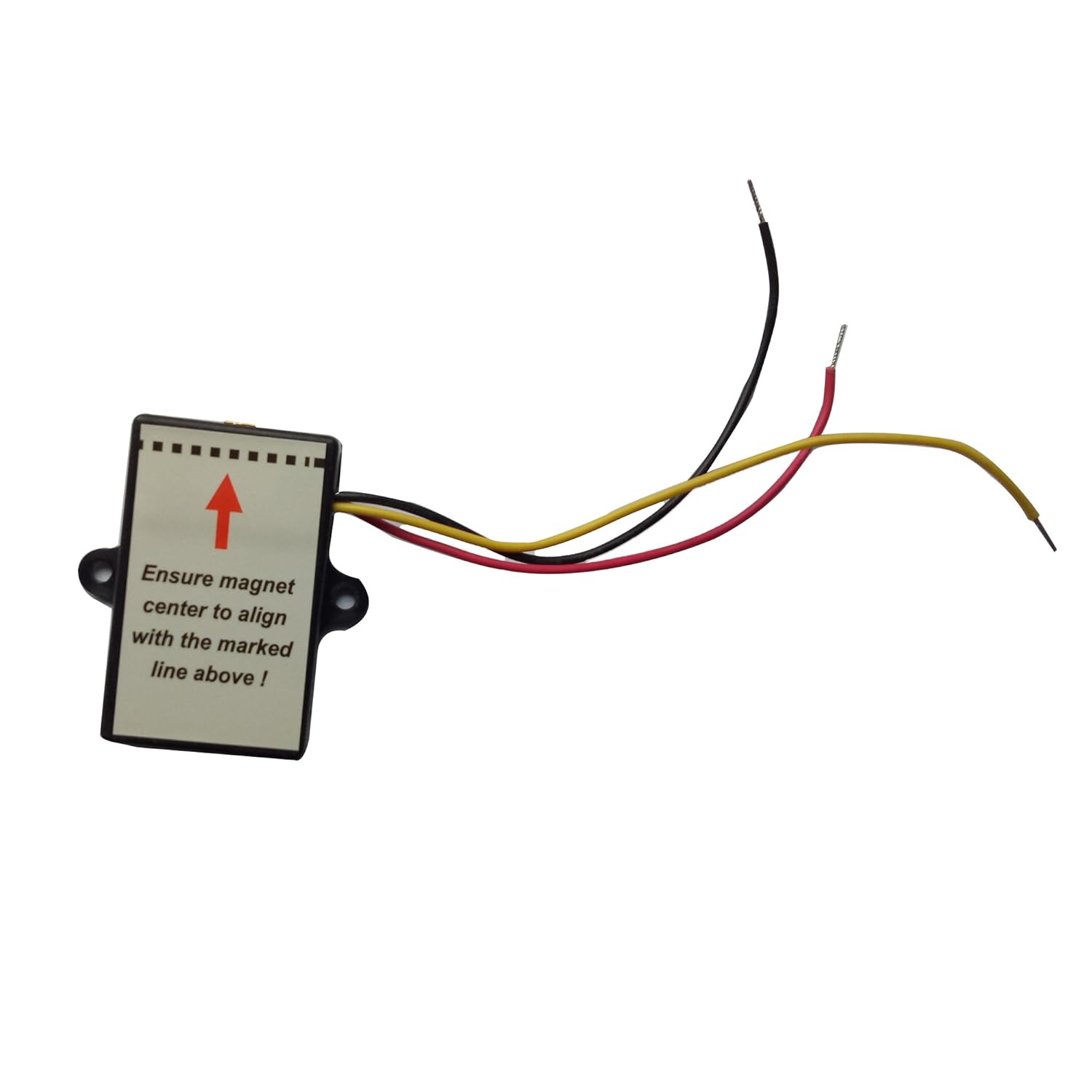
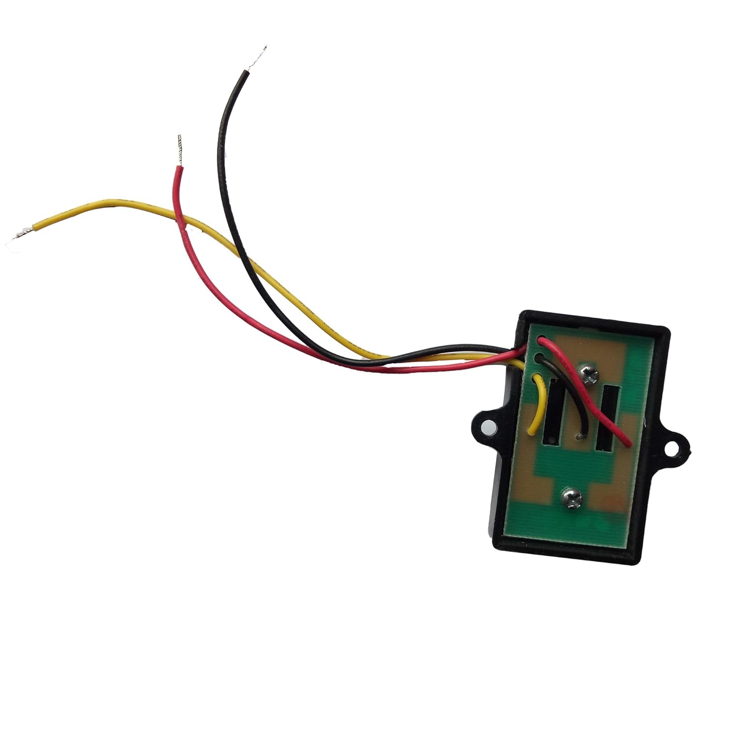
Terminal 6 “OPSW” and Terminal 5 “COM”:
Function: Accept the signal input of the gate opening, usually connected to the normally open output of a vehicle sensor.
Notes:
- When a vehicle is detected, the two terminal are shorted and the gate opens. The terminals are dedicated to opening the gate but will not close or stop the gate.
- Can be connected to a third-party vehicle sensor exit wand with a normally open dry contact signal output (ensure it is compatible with 24VDC or use an additional power adapter).
Terminal 7 “EDGE” and Terminal 8 “GND”:
Function: Receive signal input from an edge sensor, operating on a normally closed input basis.
Notes:
- Gate rebounds when the signal is open-circuit, provided there is an obstruction during operation.
- Compatible with third-party edge sensors with normally closed dry contact signal output.
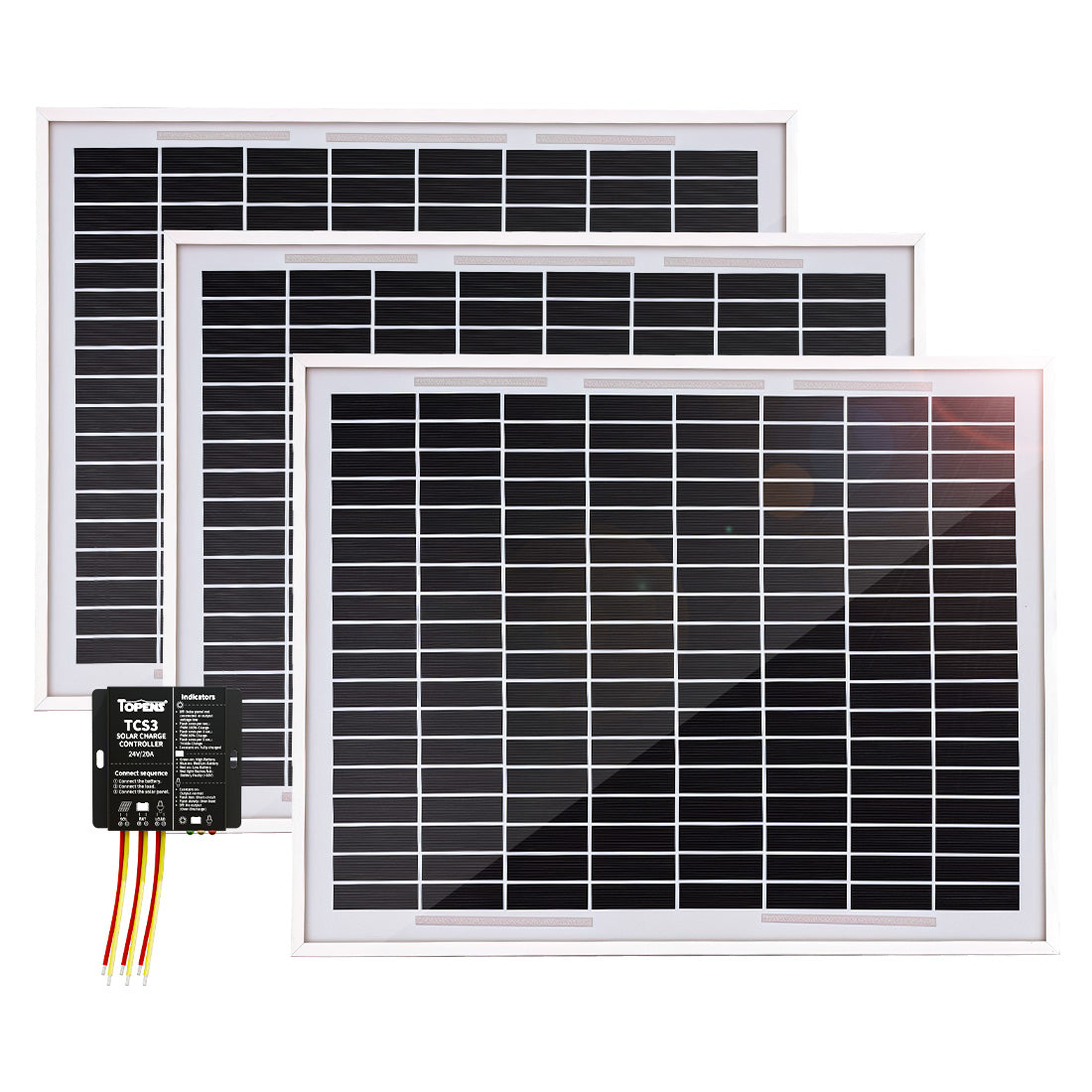
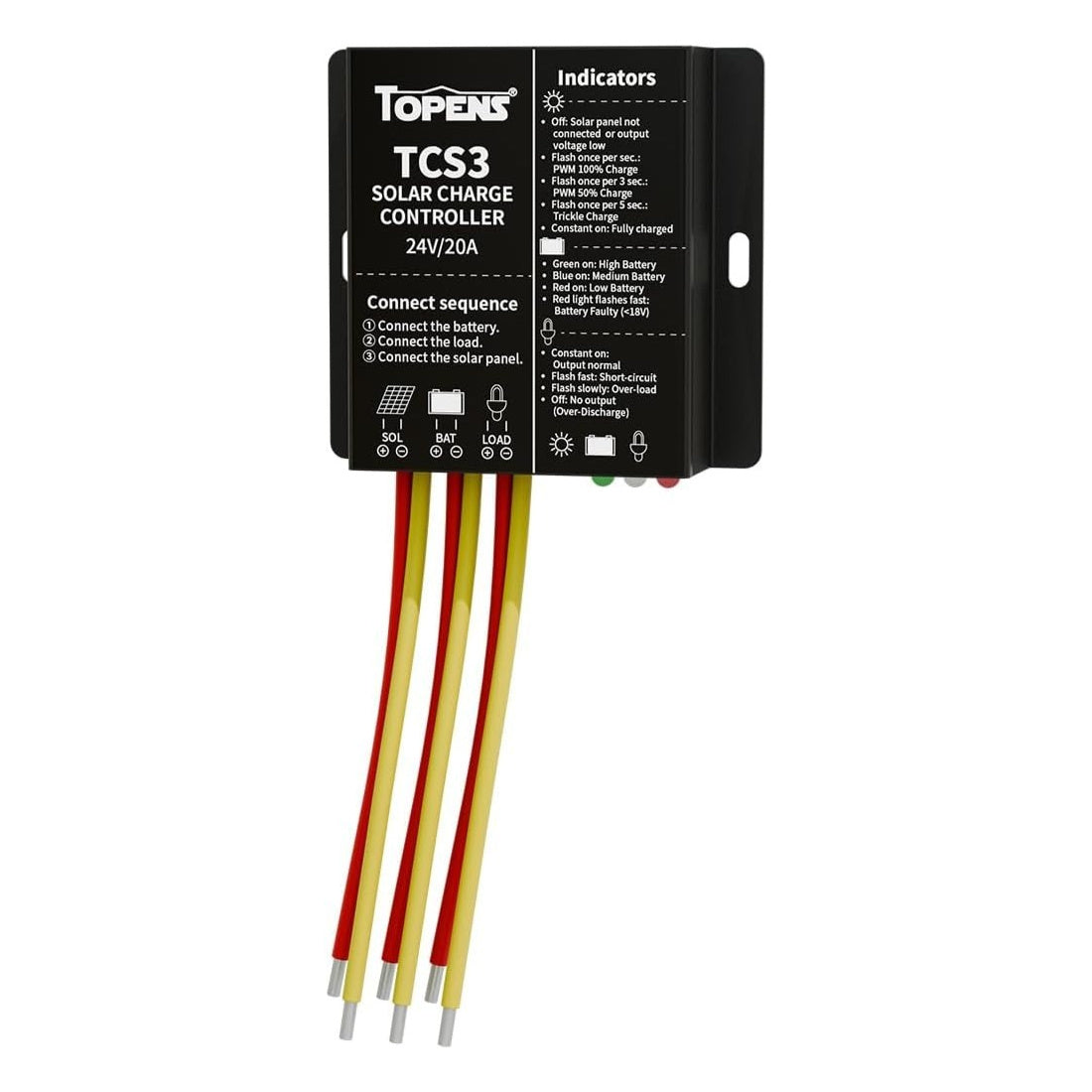
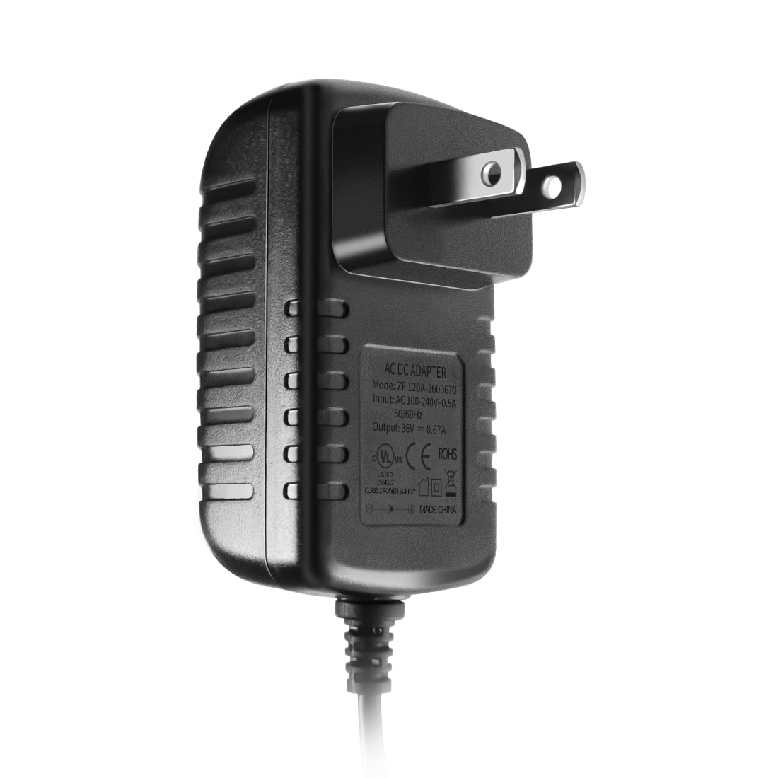
Terminals 9, 10 “ADAPTER”:
Function: Input terminals for a power adapter to charge the battery. They can also be connected to a 36VDC or 24VAC power supply for battery charging.
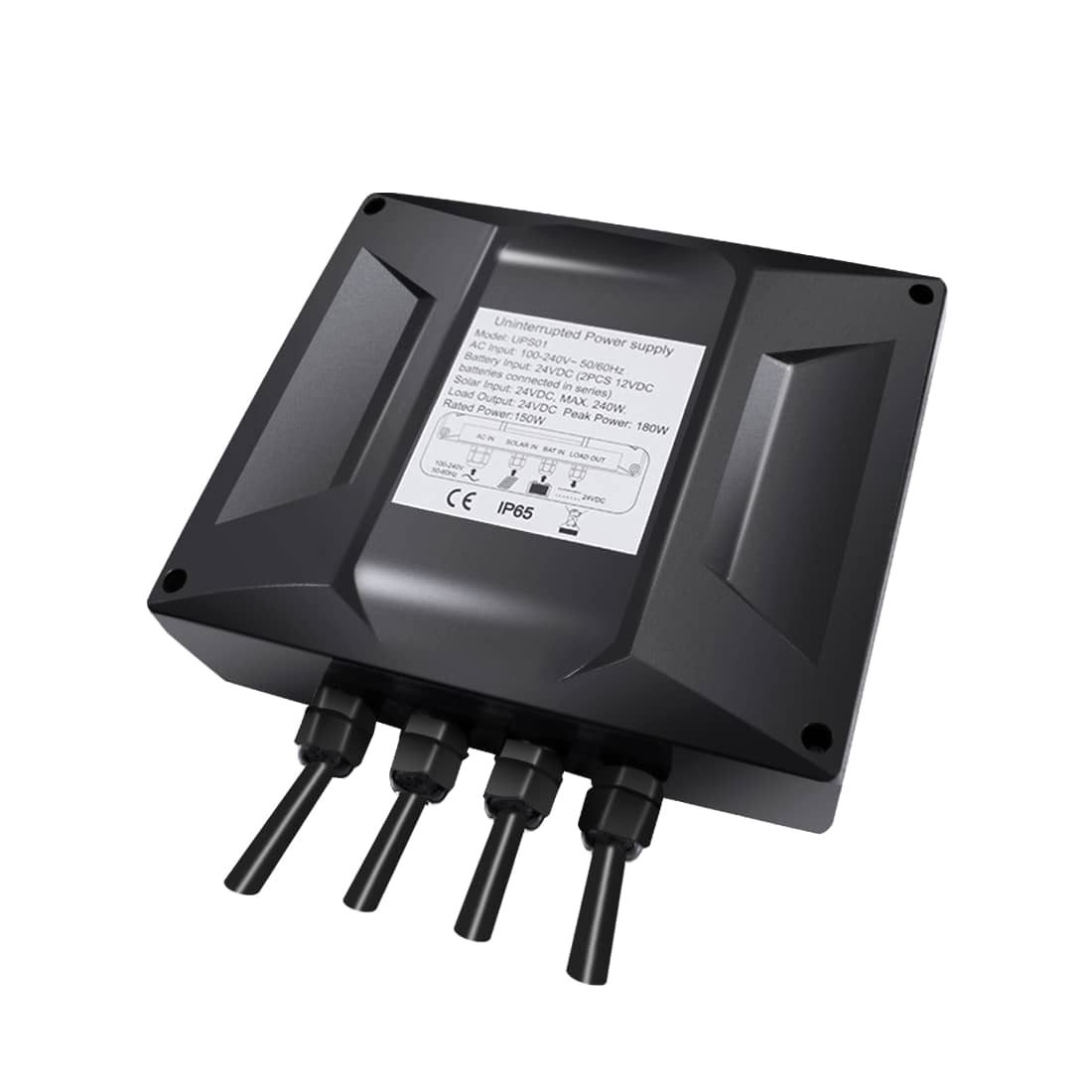
Terminals 11, 12 “+BAT-”:
Function: Input terminals for 24VDC power, typically connected to the positive and negative terminals of a 24VDC battery or 24VDC power supply, providing power to the entire system or other 24VDC accessories.
Note: Compatible with a third-party 24VDC 180W power supply.
Terminals 13, 14 “LOCK”:
Function: Output terminals for swing gate electric lock, directly connected to the positive and negative wires of the lock, providing a 24VDC voltage within the initial 4 seconds of gate opening, assuring the smooth open of the lock.
Note: Compatible with a third-party electric lock with a rated voltage of 24VDC and a rated current of less than 3A.
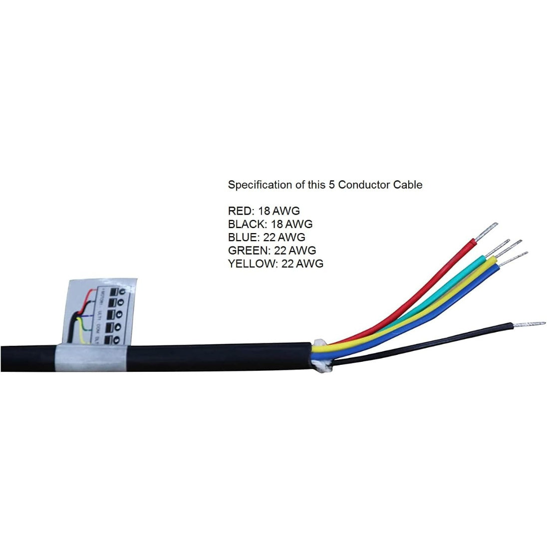
Terminals 15, 16 “MOTOR1” / Terminals 20, 21 “MOTOR2”:
Function: Connect to the red and black wires of the arm actuator.
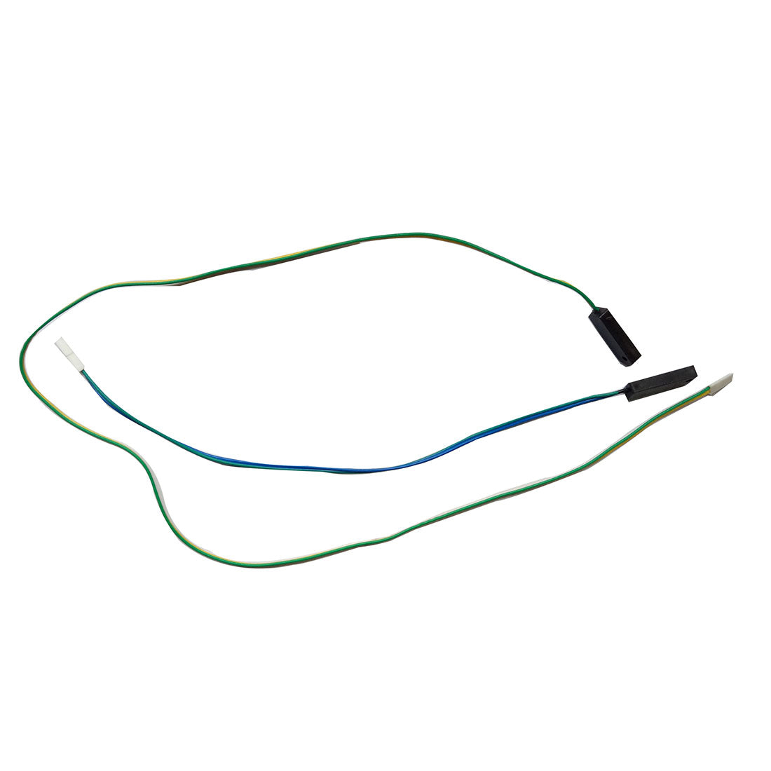
Terminal 17 “ULT1”, Terminal 18 “COM”, Terminal 19 “DLT1” / Terminal 22 “ULT2”, Terminal 23 “COM”, Terminal 24 “DLT2”:
Function: Input terminals for limit switches, with the near end limit switch connected to “ULT” and “COM” and the far end limit switch connected to “DLT” and “COM”.
Note: The green wire serves as the common line for the two limit switches, connected to the terminal “COM”.
Terminal 25, 26 “+LAMP-”:
Function: Output terminals for a warning light, connected to the positive and negative wires of the warning light, providing 24VDC voltage during gate operation to make the warning light flash.
Note: Compatible with third-party warning lights with rated voltage of 24VDC and rated current of less than 1A.
Remember, before making any adjustments or connections, always turn off the gate opener to prevent accidents and ensure your safety. Exercise caution and stay at a safe distance from the gate during system setup and configuration to avoid unexpected gate movements, further prioritizing your well-being.
Each terminal on the EKPKMJ4B control board plays a specific role. By understanding and effectively using these terminals, you can optimize the performance of your gate opener, making your access control system more reliable, secure, and convenient.

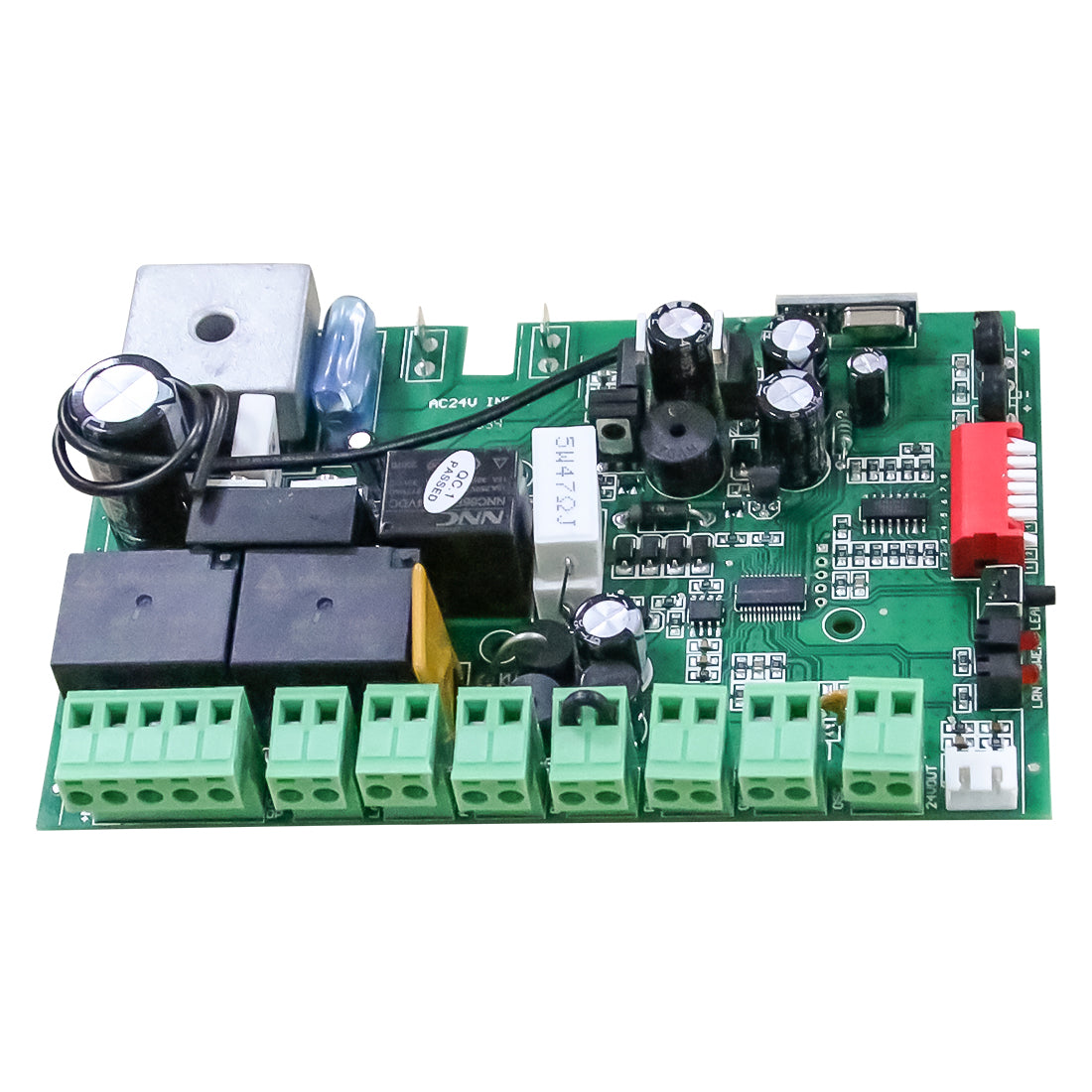
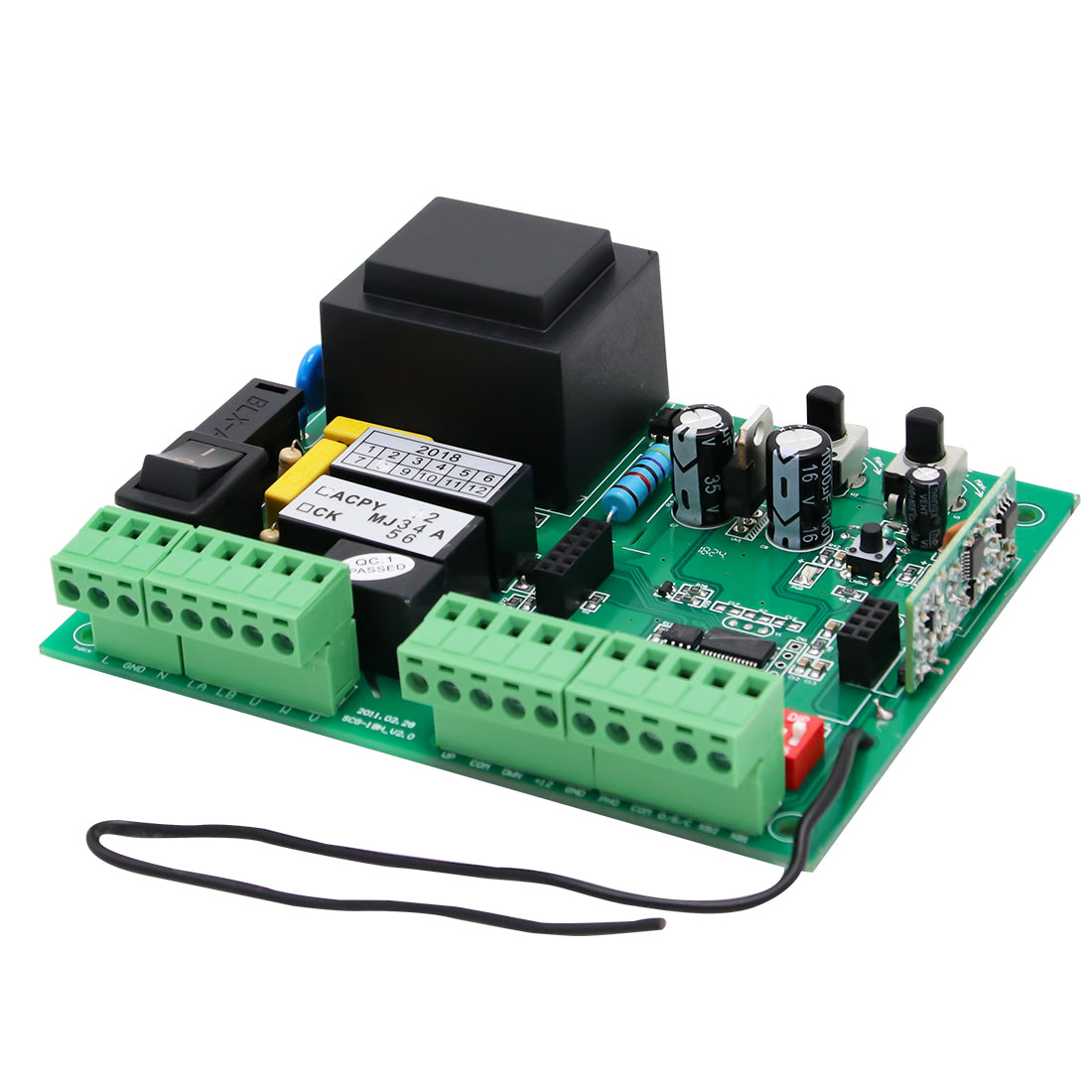
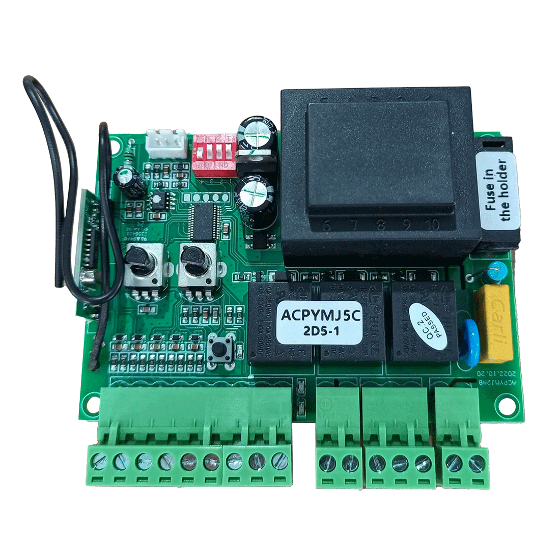
The terminals on the other control board of TOPENS swing gate opener are basically unanimous, which you can take EKPKMJ4B for reference. If you have any further questions or need assistance, refer to the gate opener's user manual or reach out to our support team for expert guidance. Your satisfaction and safety are our highest priorities.