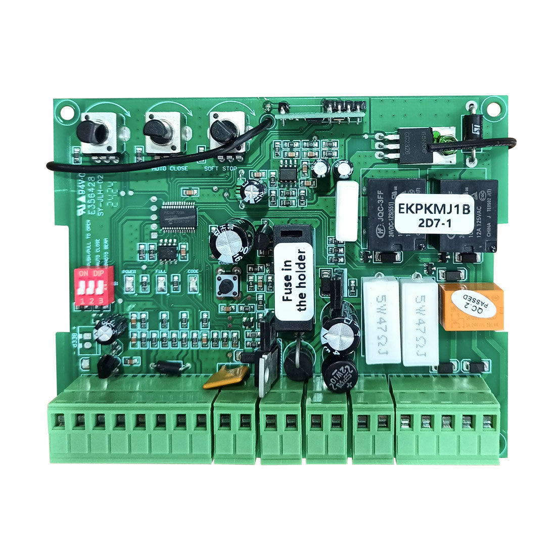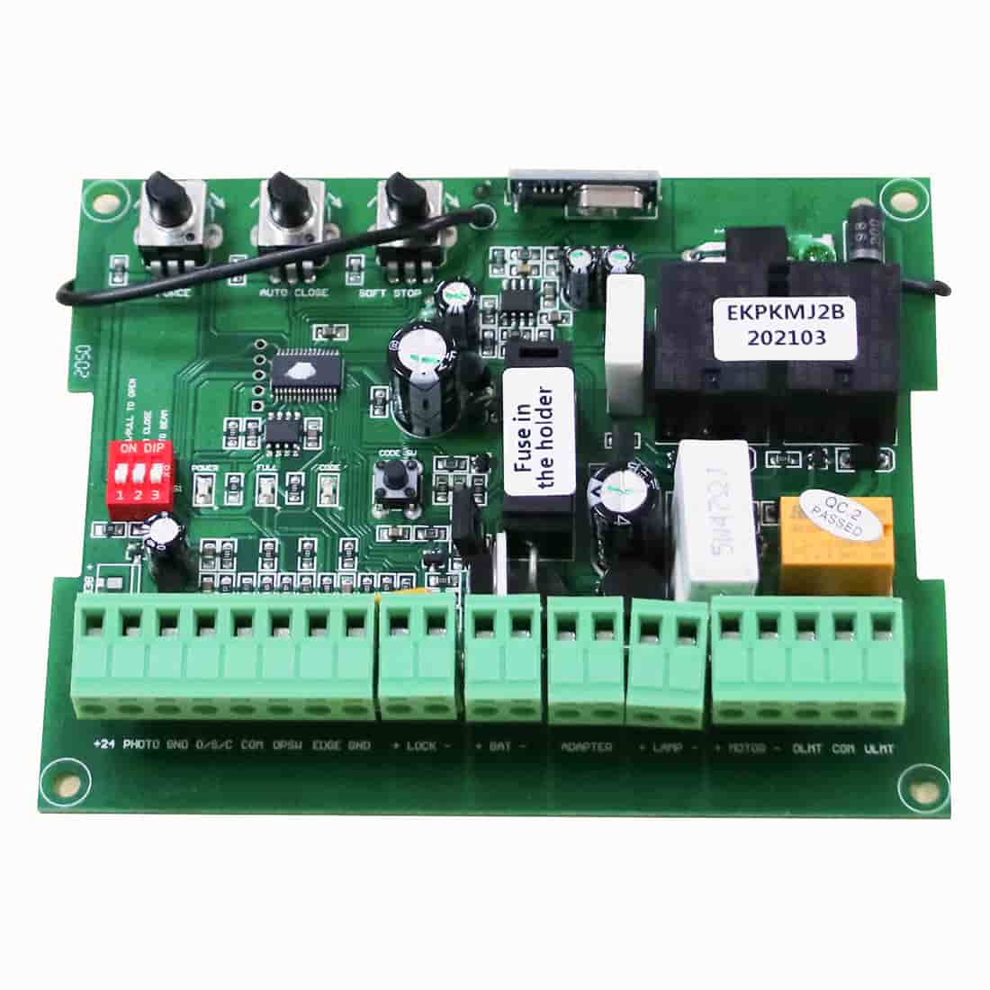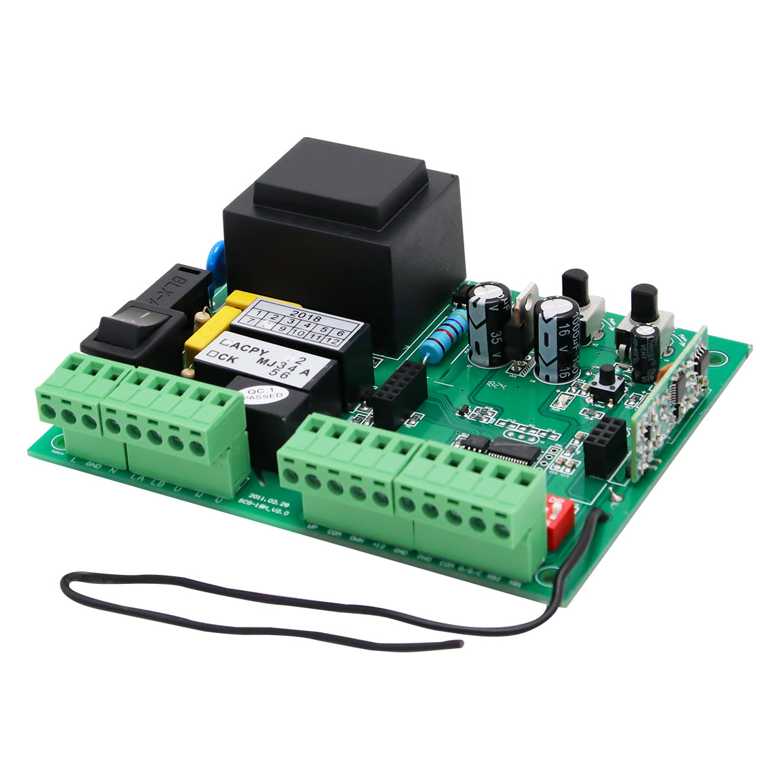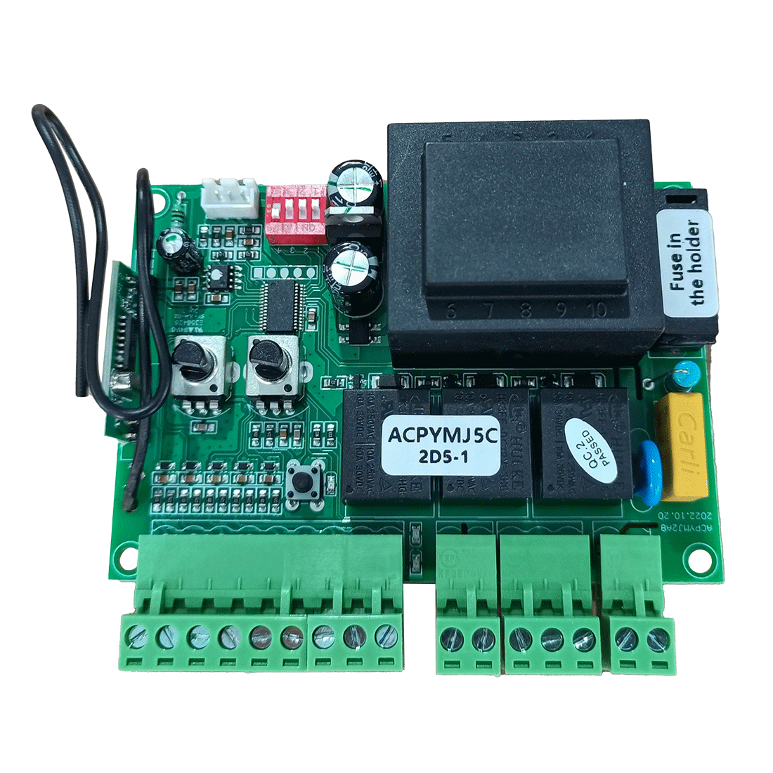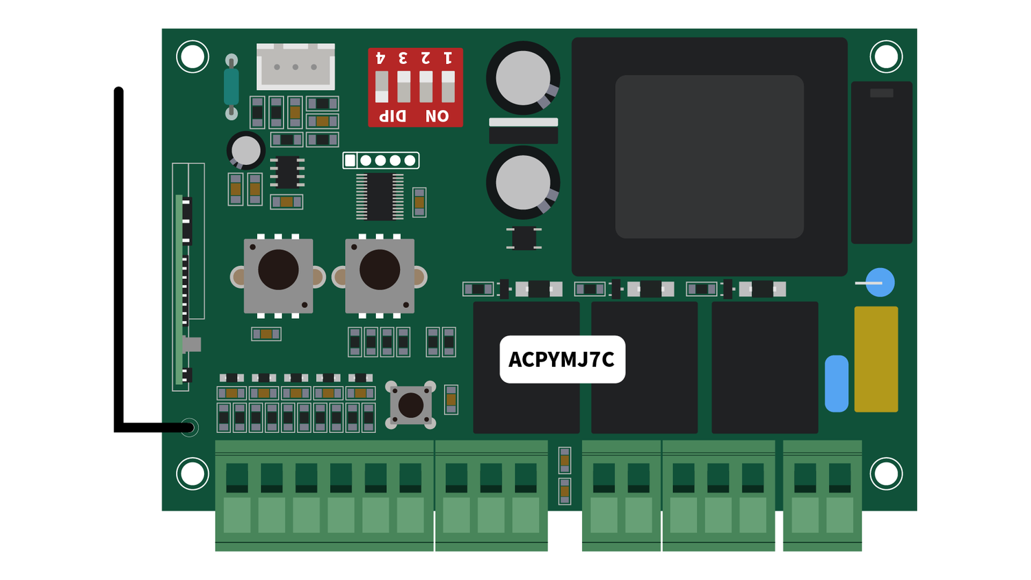
To ensure an optimal experience with your TOPENS sliding gate opener, it is crucial to comprehend the functions of the wiring terminals on its control board. This article aims to provide a clear understanding of your sliding gate opener system by focusing on the ACPYMJ7C control board in TOPENS CK1100 model.


| Terminal | Full Name |
| 1. L | LIVE WIRE |
| 2. N | NEUTRAL WIRE |
| 6-7. LAMP | LAMP |
| 8. DN | DOWN LIMIT |
| 9. COM | COMMON |
| 10. UP | UP LIMIT |
| 11. VCC | VOLTAGE AT THE COMMON COLLECTOR |
| 12. PHO | PHOTOCELL |
| 13. COM | COMMON |
| 14. O/S/C | OPEN/STOP/CLOSE |
| 15. COM | COMMON |
| 16. OPSW | OPEN SWITCH |
Key Note:
Each terminal is interdependent. Accessory connections require the use of multiple terminals simultaneously.
Terminals and Their Functions:
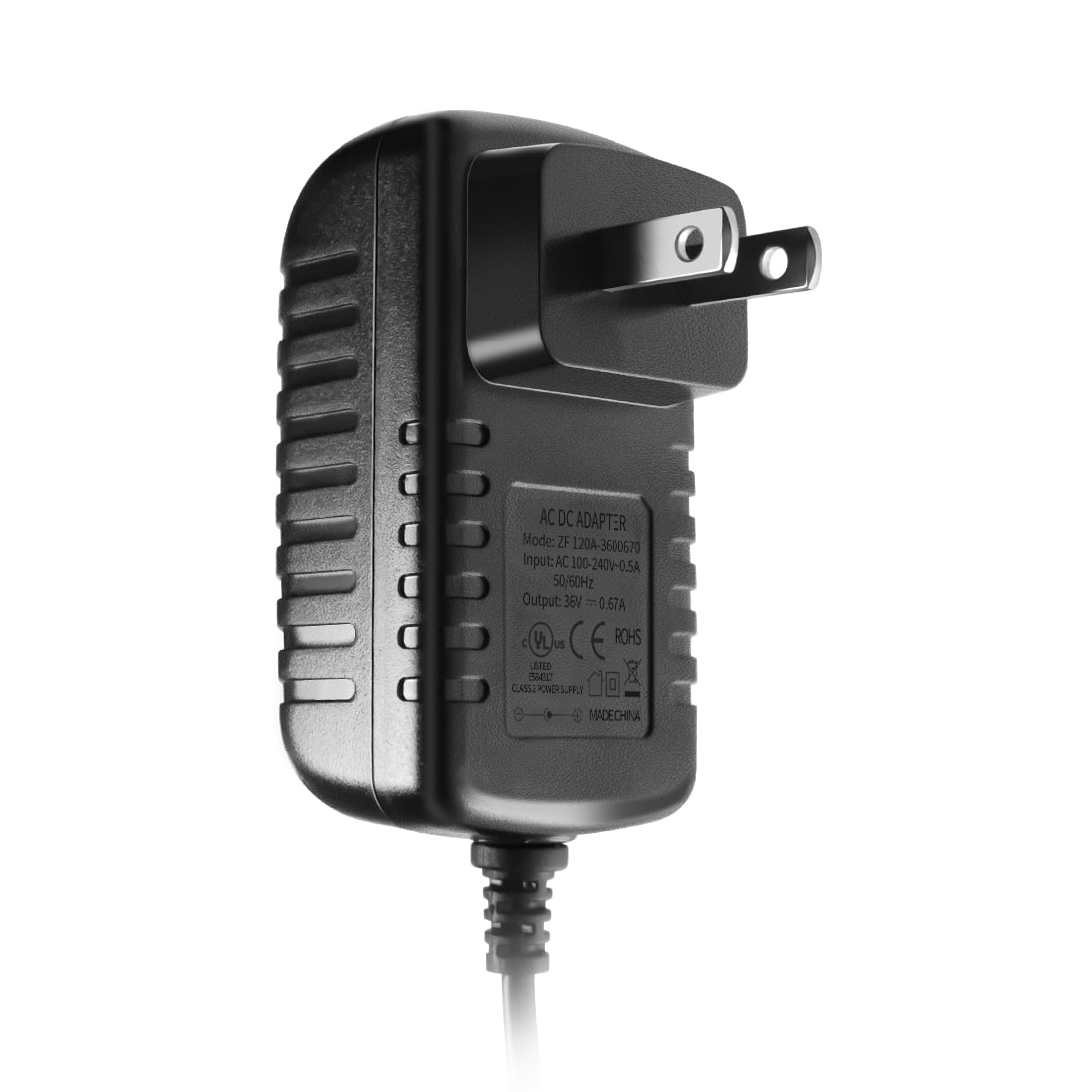
Terminal 1 “L” and Terminal 2 “N”:
Function: Input terminals for AC power, connected to the live (L) and neutral (N) wires of the power supply cord.
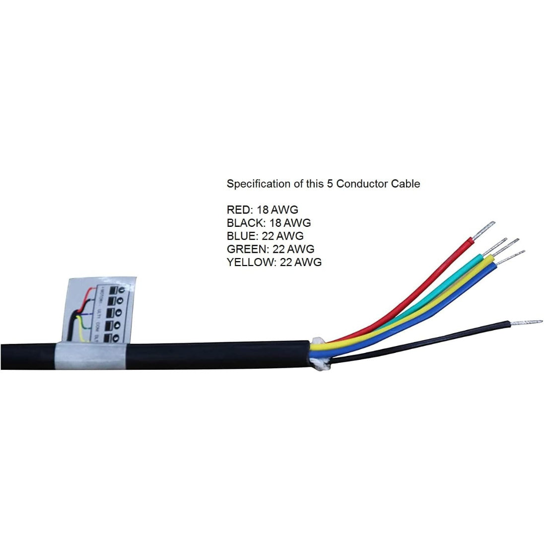
Terminal 3 “U”, Terminal 4 “V”, and Terminal 5 “W”:
Function: Output terminals for motor control, connected to the motor wires (black, yellow, and red) respectively. The starting capacitor wires are connected in parallel with motor wires (yellow/black) to “V” and “W” terminals.
Note: Terminal “U” serves as the common end, while terminals “V” and “W” control the motor direction (forward/reverse).
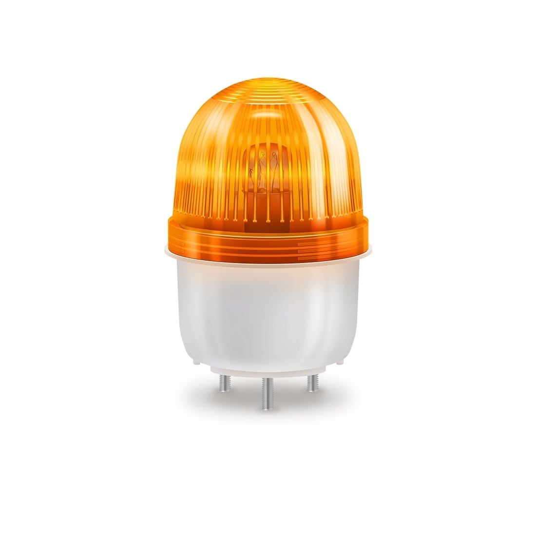
Terminal 6, 7 “LAMP”:
Function: Output terminals for a warning light, directly connected to the warning light, providing the same voltage as the mains supply during gate operation, making the warning light flash.
Note: Compatible with third-party warning lights with rated voltage matching motor voltage and rated current of less than 1A.
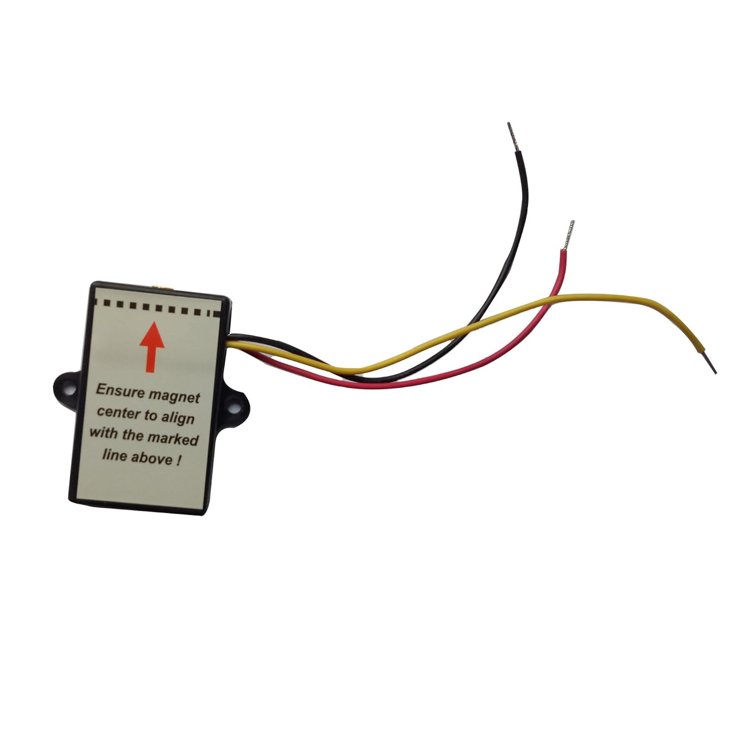
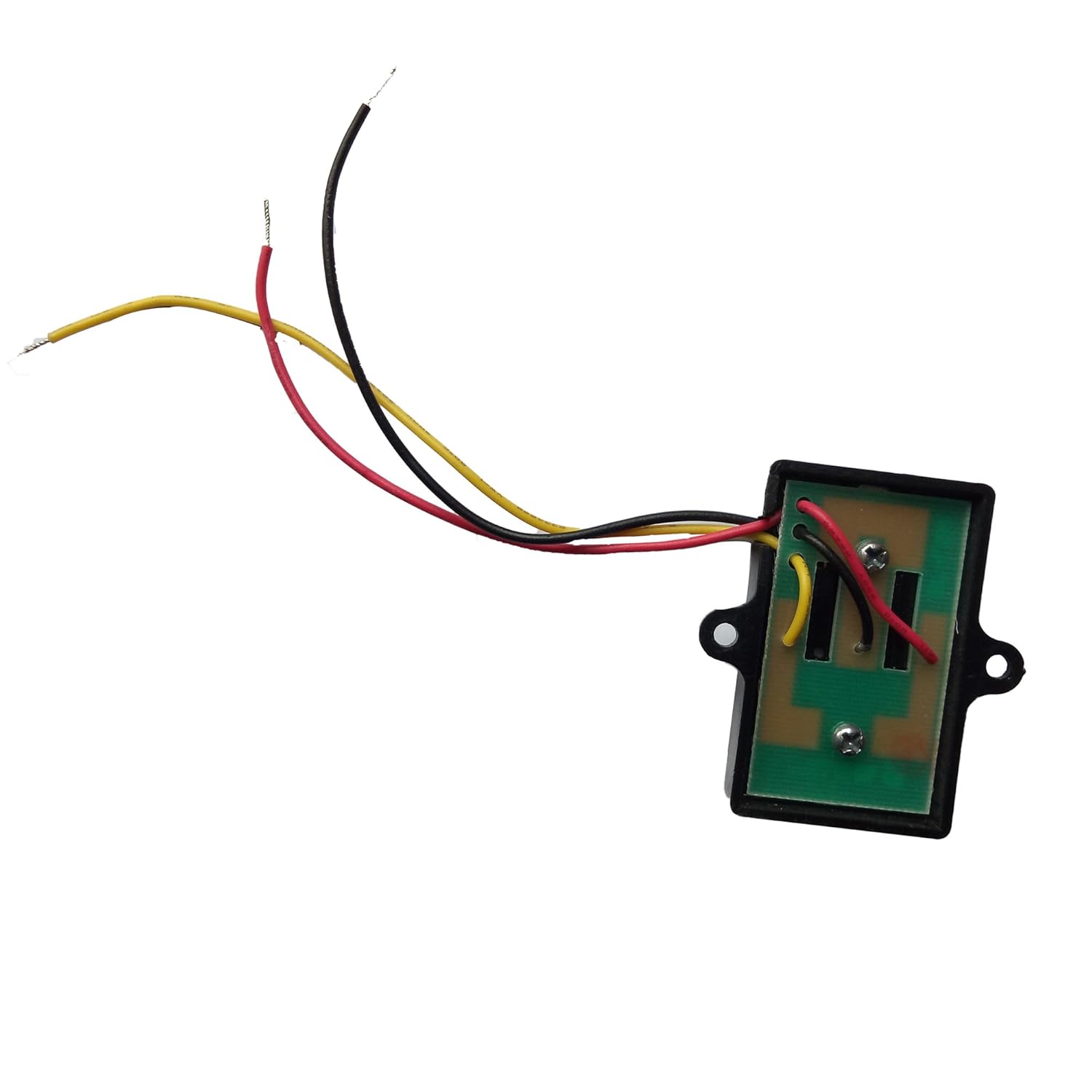
Terminal 8 “DN”, Terminal 9 “COM”, and Terminal 10 “UP”:
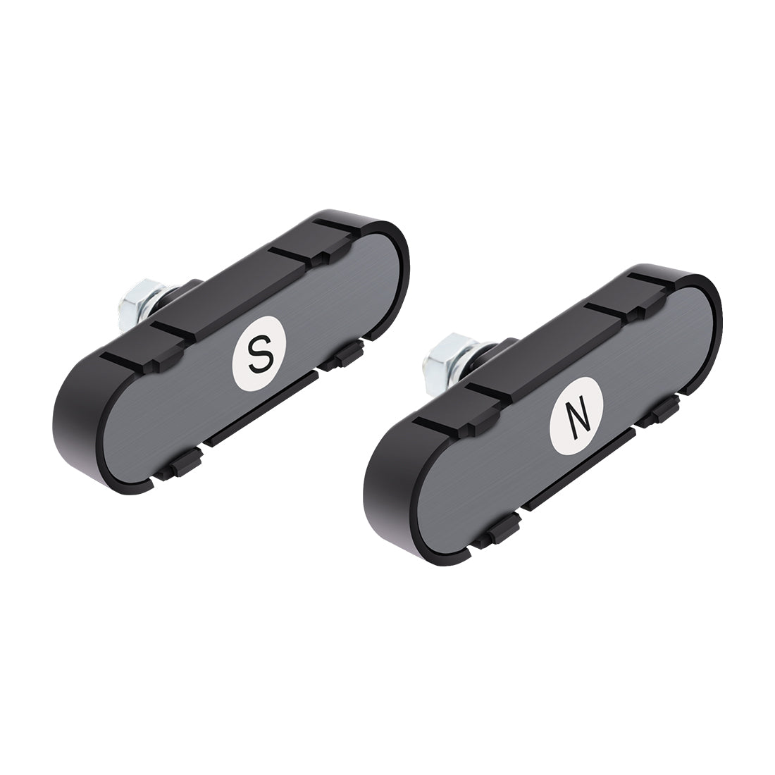
Function: Input terminals for normally closed limit switches, connected to the yellow, black and red wires of the limit switch, respectively. When the magnet triggers the limit switch, the normally closed limit switch contact is open-circuit and the motor stops running.
Terminal 11 “VCC” and Terminal 13 “COM”:
Function: Auxiliary output terminals, providing 12VDC power to accessories (rated output less than 100mA).
Note: Can power third-party accessories with a rated voltage of 12VDC.
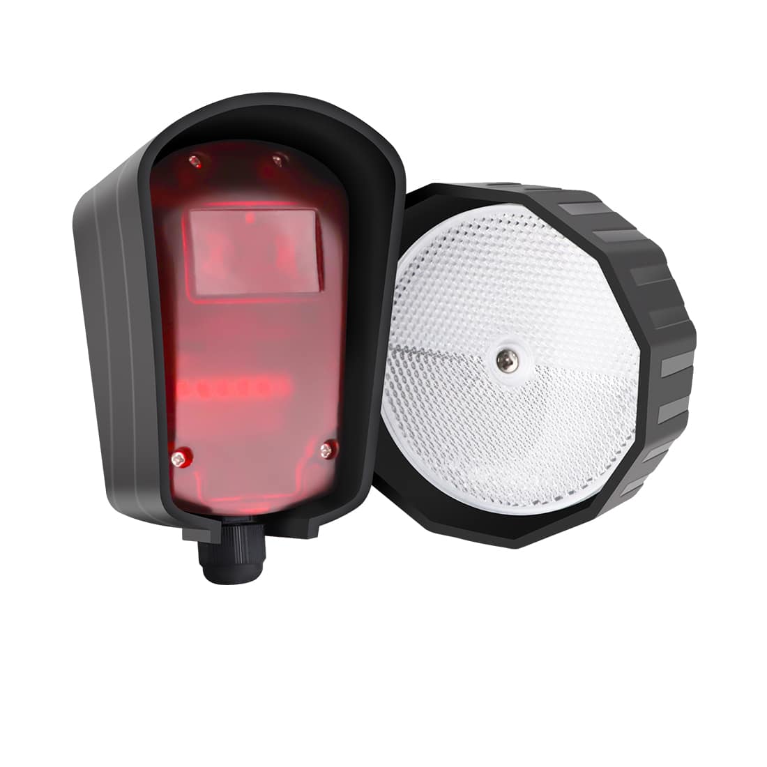
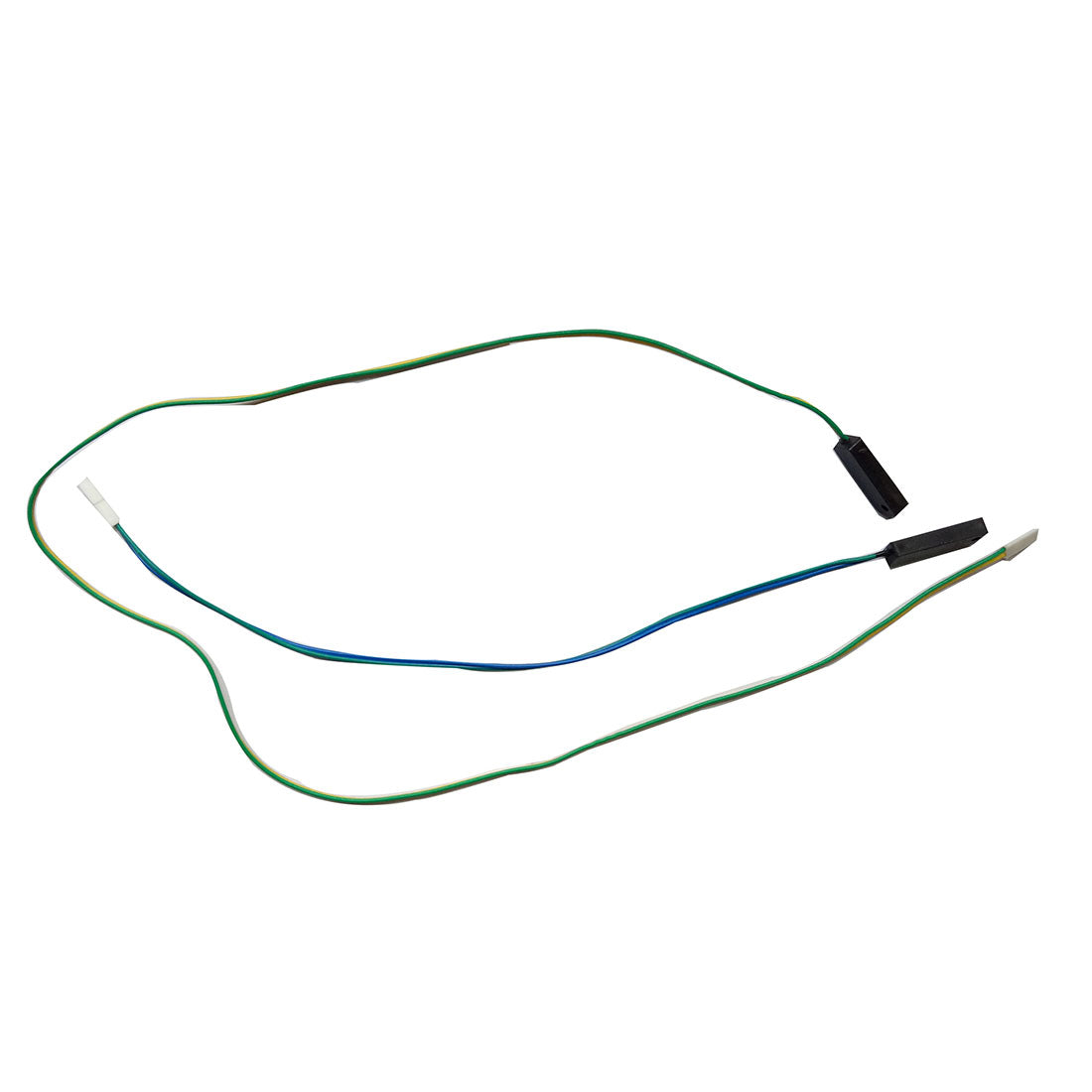
Terminal 12 “PHO” and Terminal “COM”:
Function: Receive signal input from a photoelectric beam sensor, operating on a normally closed (NC) input basis (NC: normally closed; NO: normally open).
Notes:
- The gate responds based on sensor status (blocked or unblocked). Sensor blockage makes the two terminals open-circuit, prompting the gate to stop or reverse accordingly.
- Connection to a third-party photo sensor with normally closed dry contact signal output is possible.
Terminal 14 “O/S/C” and Terminal 13 “COM”:
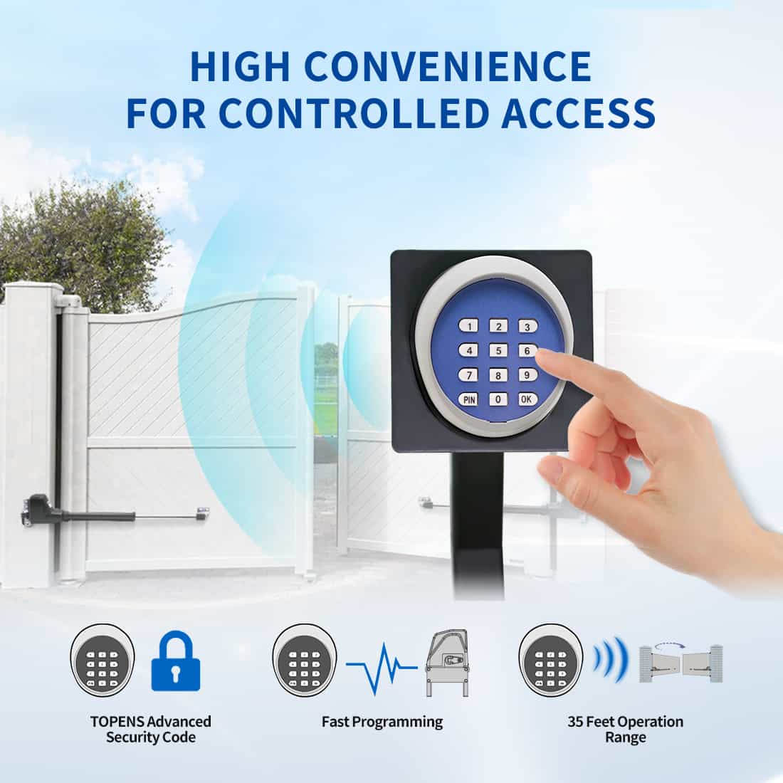
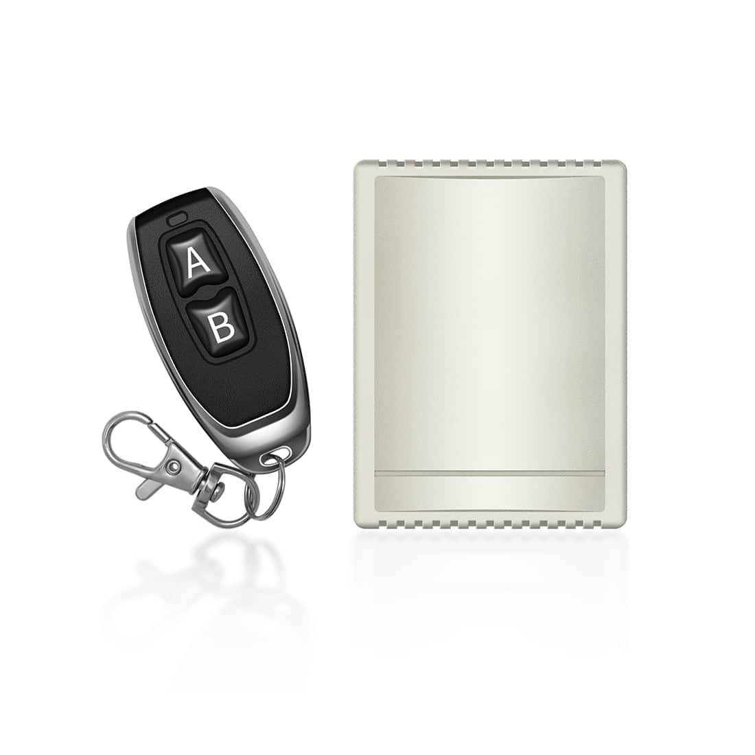
Function: Control gate operation through a normally open dry contact signal input, commonly connected to push button, wired keypad, and external receiver for cyclic gate operation (open/stop/close/stop).
Note: Compatible with third-party push buttons, wired keypads, or external receivers with normally open dry contact signal output.
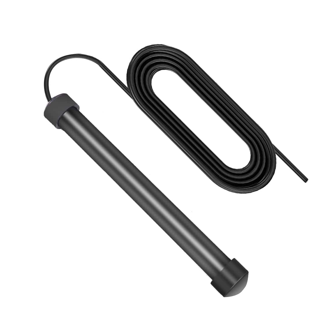
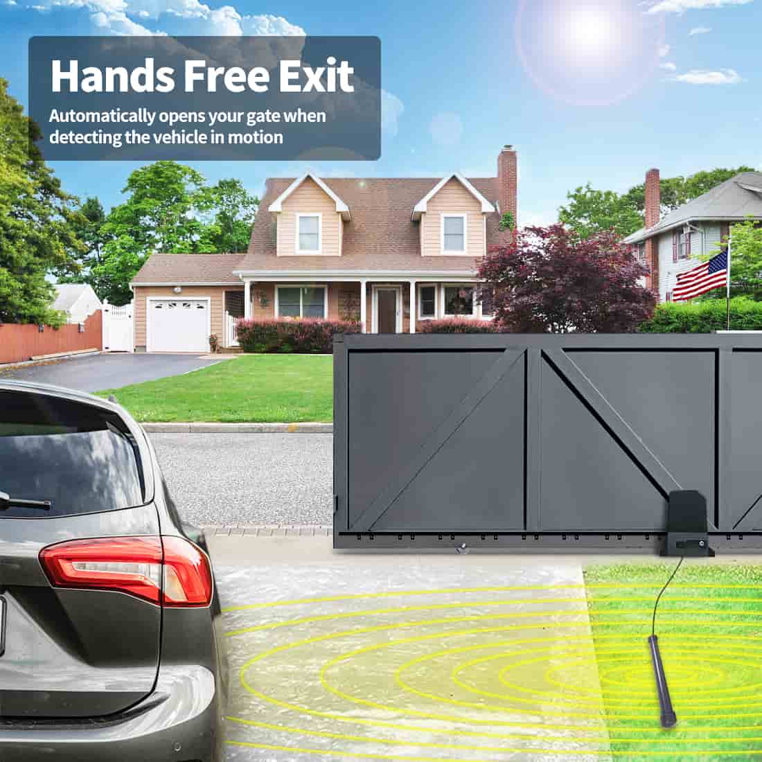
Terminal 16 “OPSW” and Terminal 15 “COM”:
Function: Accept the signal input of the gate opening, usually connected to the normally open output of a vehicle sensor exit wand.
Notes:
- When a vehicle is detected, the two terminals are shorted, triggering the gate to open. The terminals are dedicated to opening the gate but will not close or stop the gate.
- Can be connected to a third-party vehicle sensor exit wand with a normally open dry contact signal output (ensure it is compatible with 12VDC or use an additional power adapter).
Tips:
The compatibility of the control board with third-party accessories depends on the rated voltage of the accessory and its type of signal output. Select accessories accordingly for seamless integration.

Understanding the terminal functions on the control board of your TOPENS sliding gate opener is a fundamental step towards optimal operation and troubleshooting. By familiarizing yourself with how each terminal operates and its intended functions, you can make informed decisions and efficiently integrate the necessary accessories.
Always prioritize safety. Adhere to the safety guidelines provided in the user manual during any installation, setup, or maintenance procedures. If you encounter challenges or have further questions about your TOPENS sliding gate opener system, feel free to consult the comprehensive user manual or contact our dedicated support team.
We value your satisfaction and are committed to ensuring a smooth and secure experience with your gate opener. Thank you for choosing TOPENS for your access control needs!