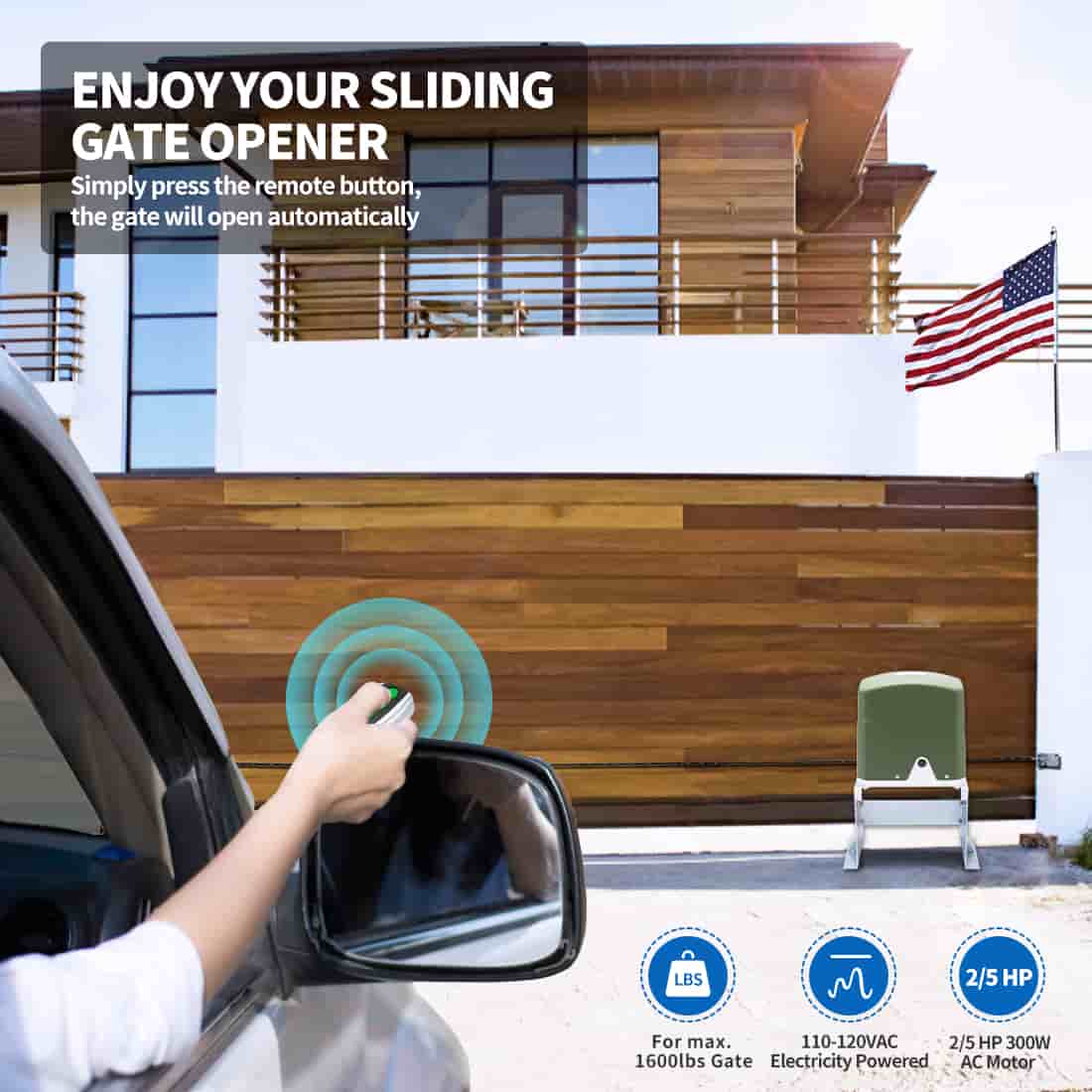
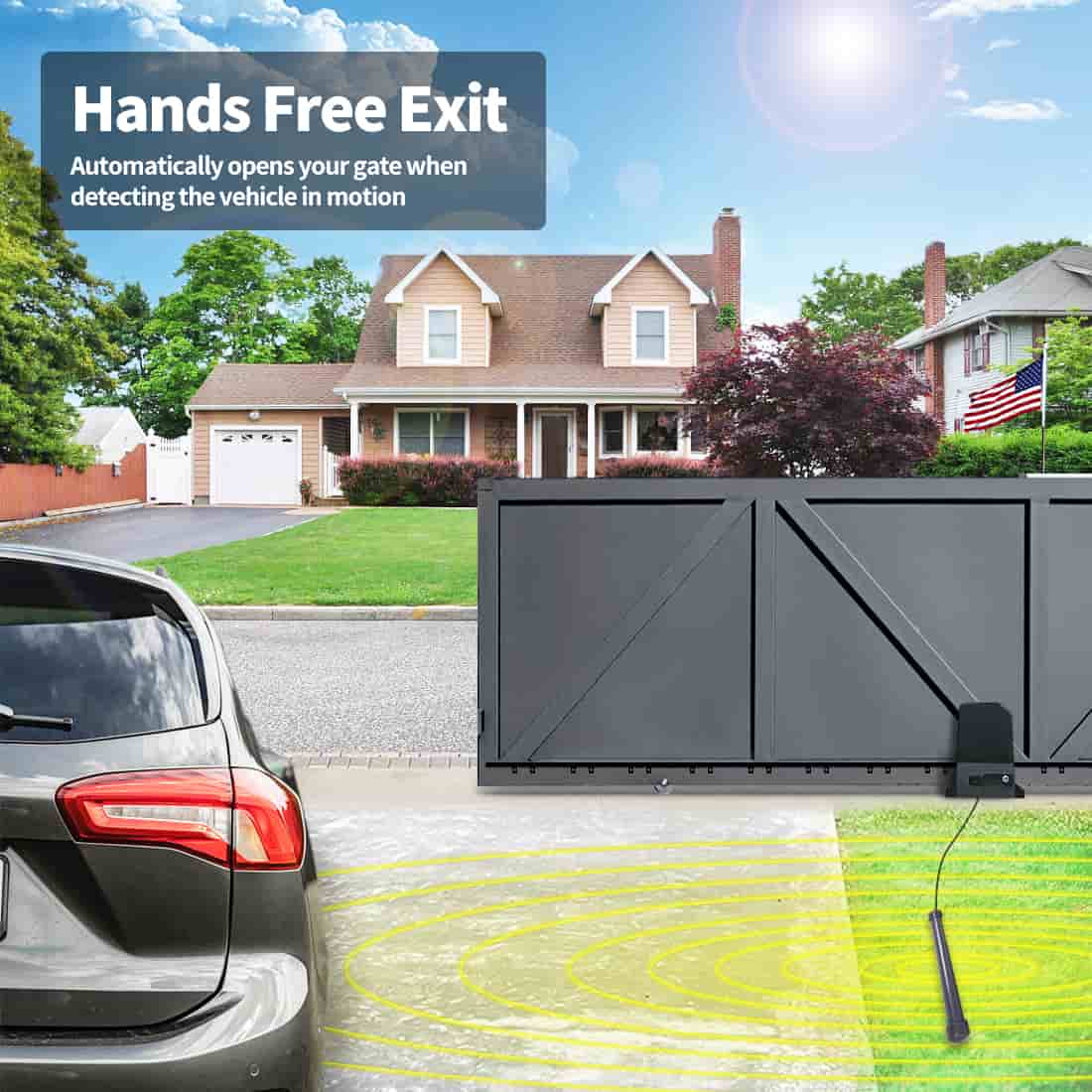
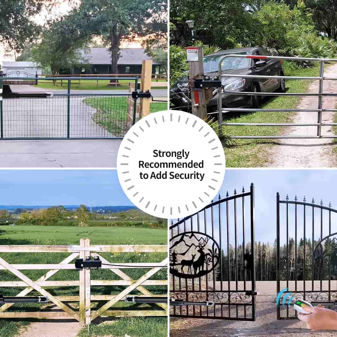
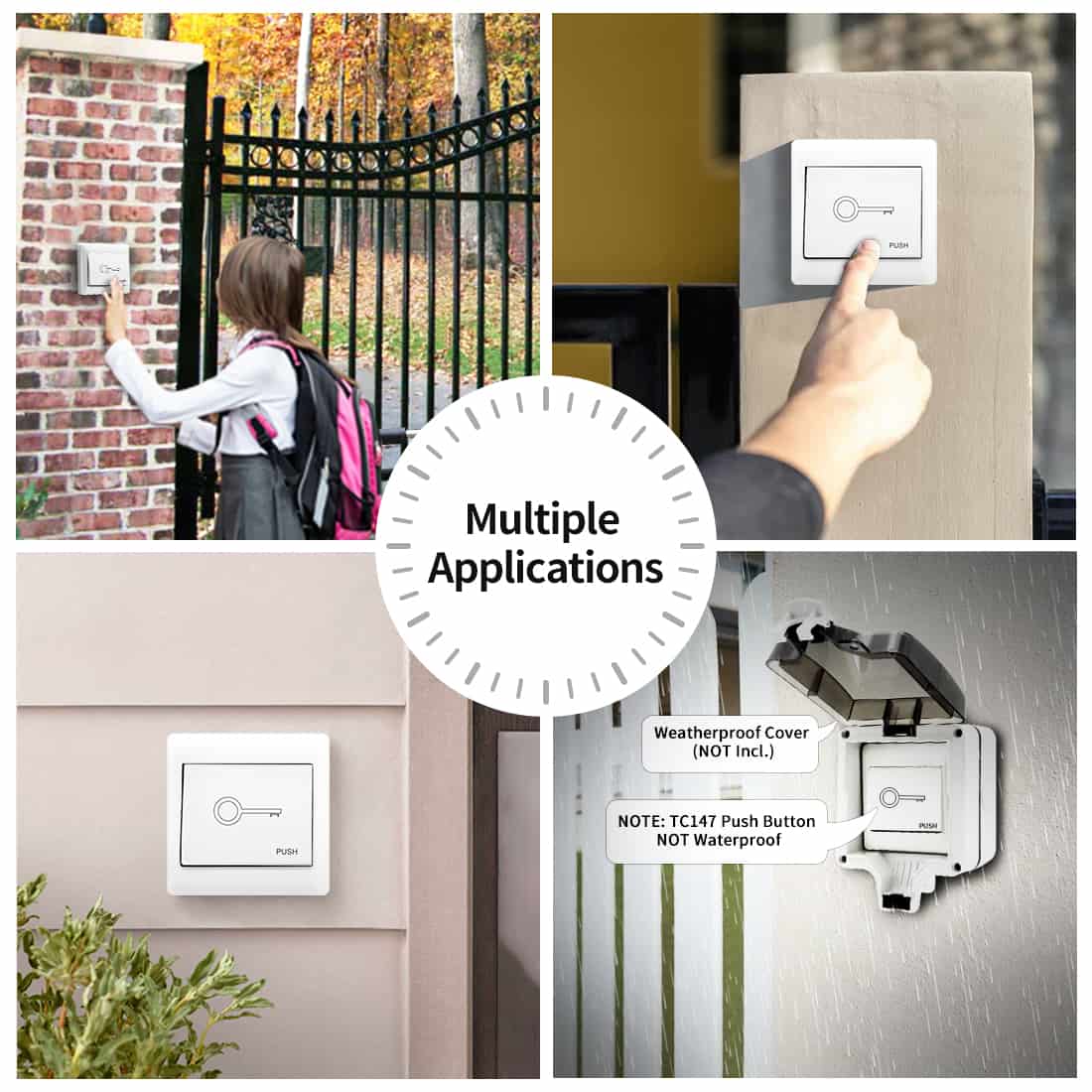
Automatic gate openers have become increasingly popular for their convenience and enhanced security. To ensure the safe operation of these systems, it is essential to install appropriate safety devices such as retro-reflective photocell sensors. Today we will take you through the step by step process of installing TOPENS TRF3 Retro-Reflective Photocell Sensor.
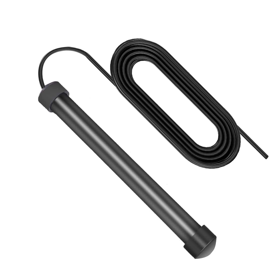
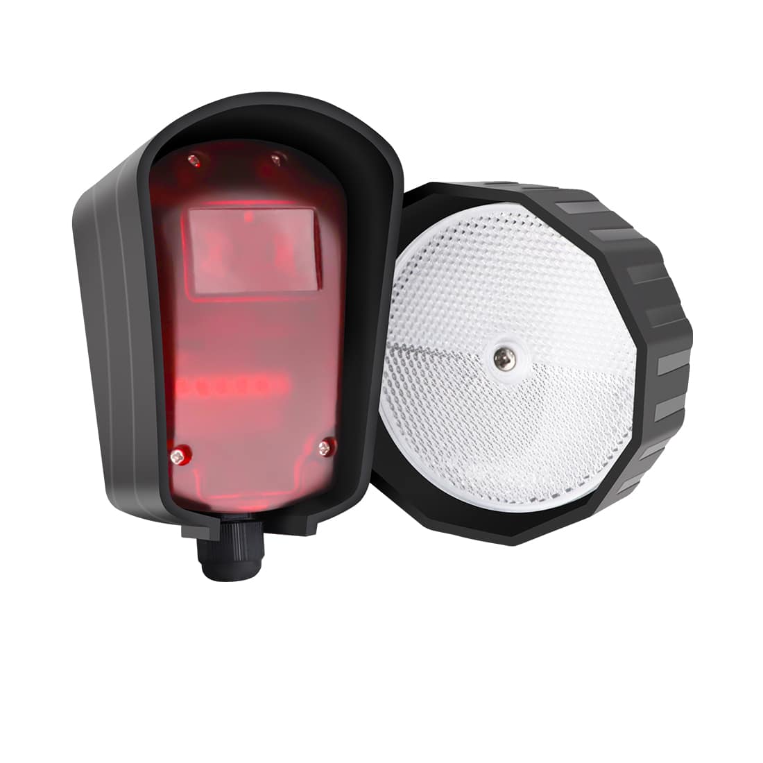
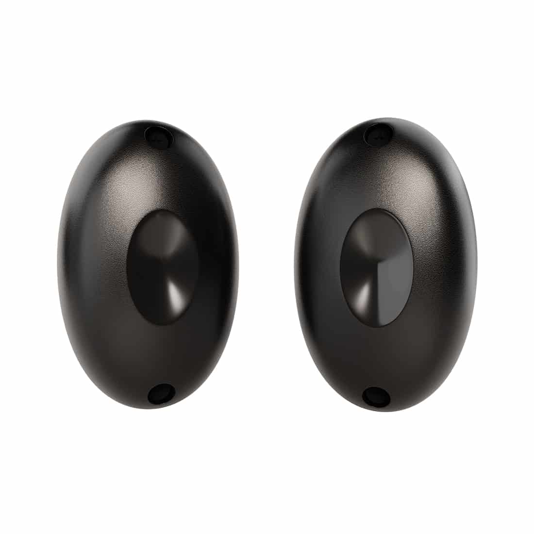
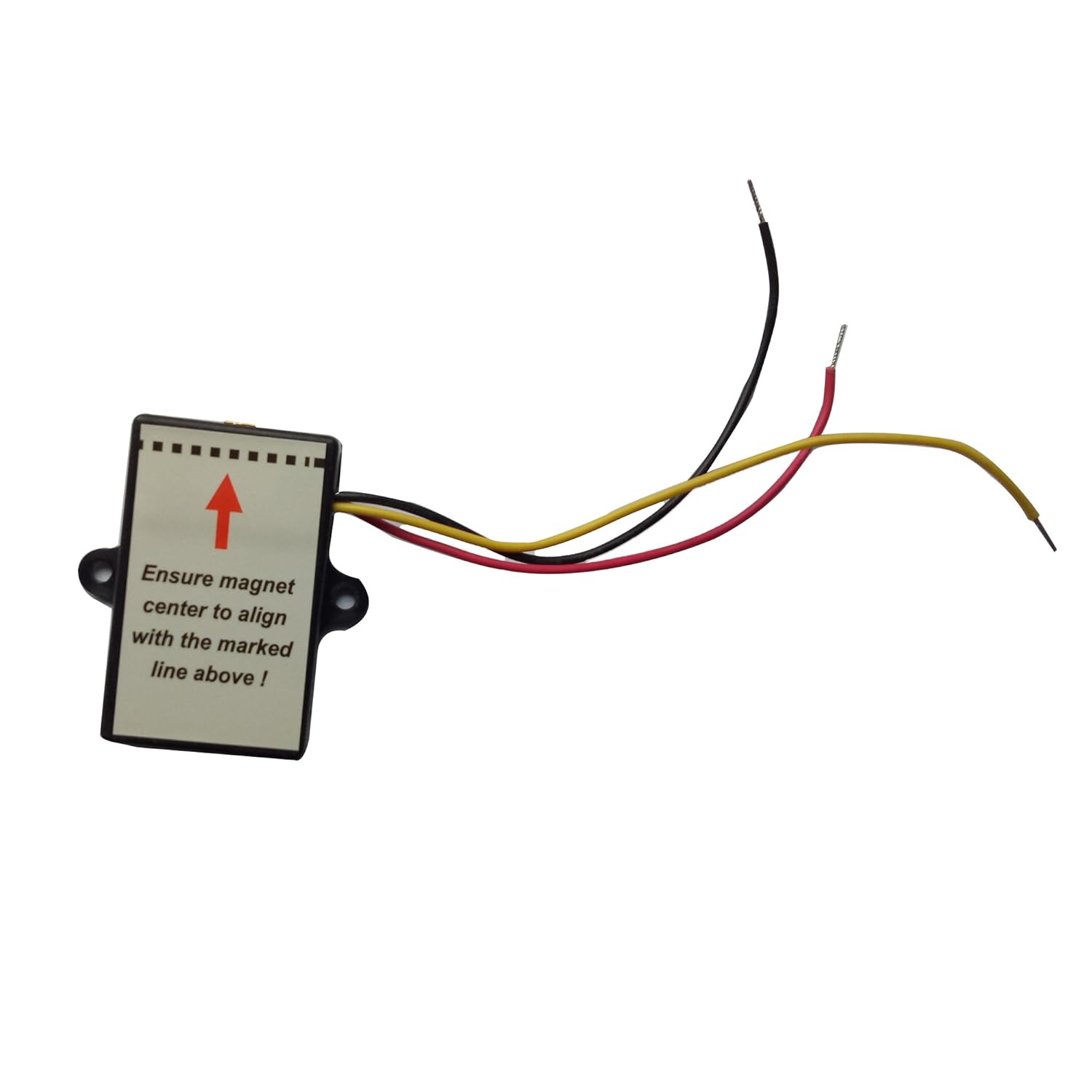
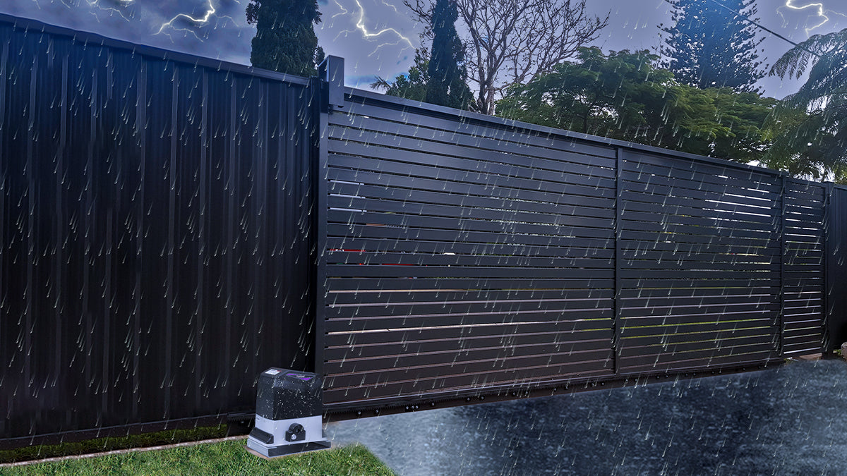
TRF3 Retro-Reflective Photocell Sensor
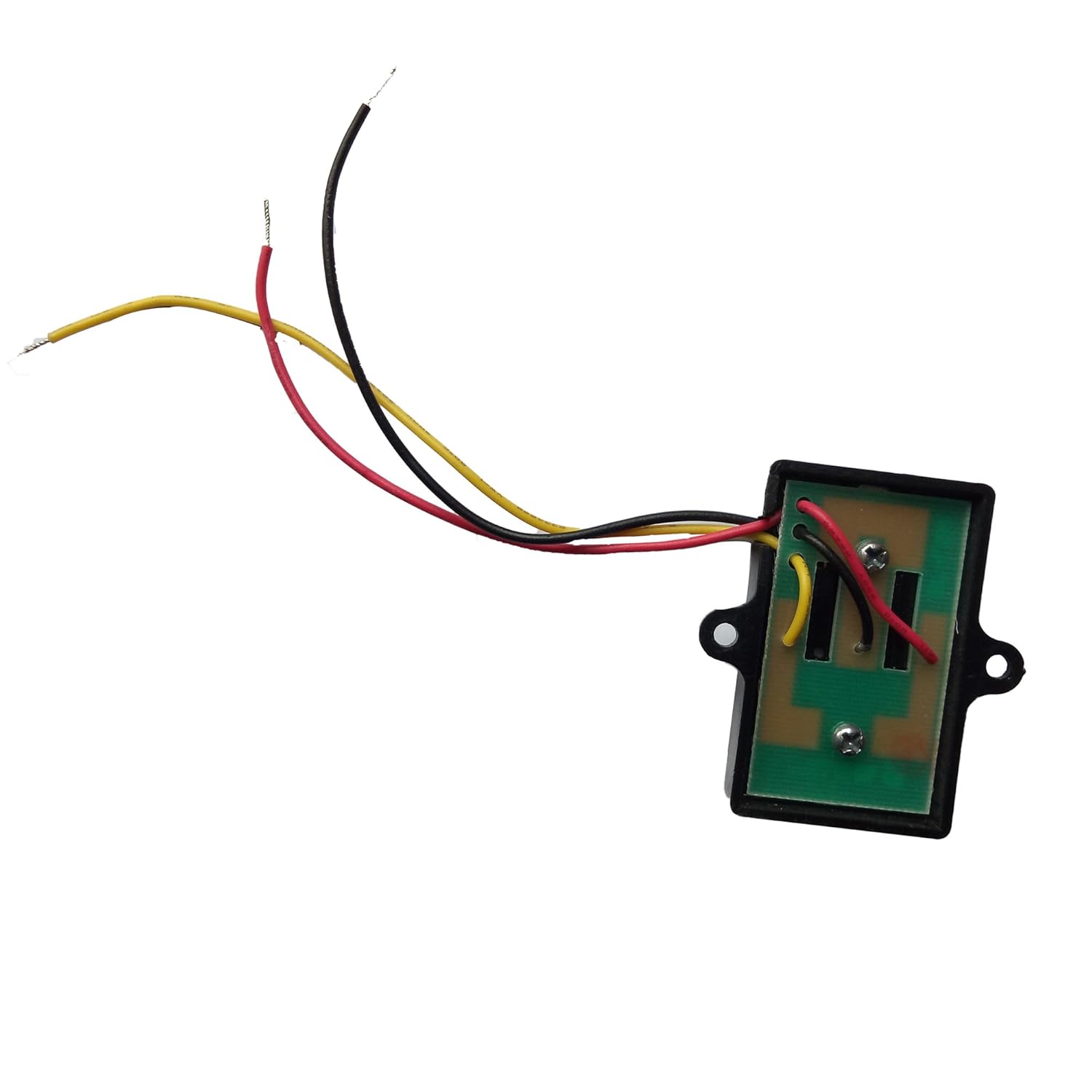
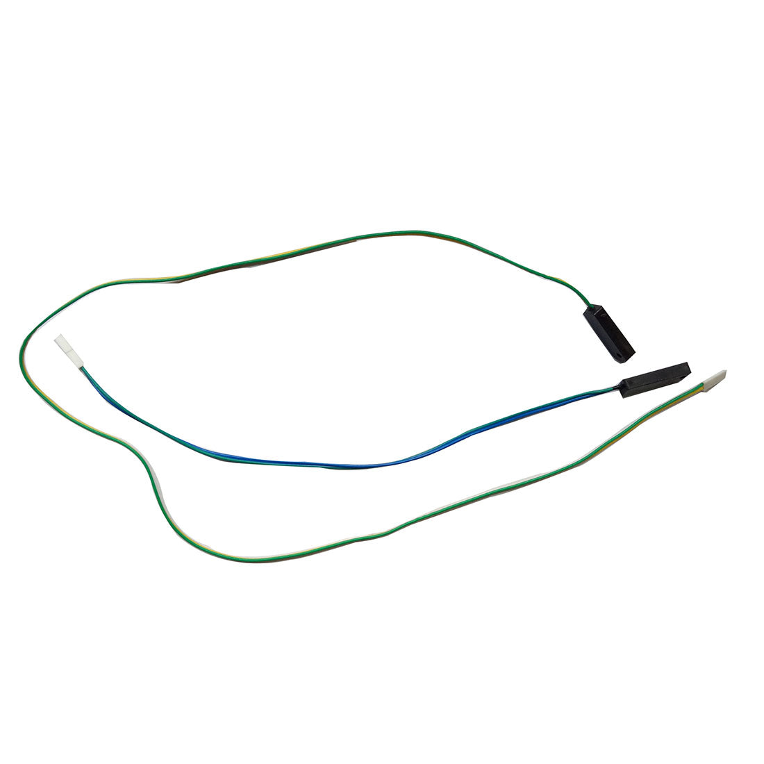
This device consists of a retro-reflective photocell and a reflector. Both the light beam emitter and detector elements are integrated into the photocell, and the separate reflector is designed to reflect the emitted beam back to the sensor. When the beam is interrupted, the sensor triggers the gate opener to stop or reverse its operation, preventing accidents or damage.
Installation Steps:
Step 1: Gather the Necessary Tools and Materials
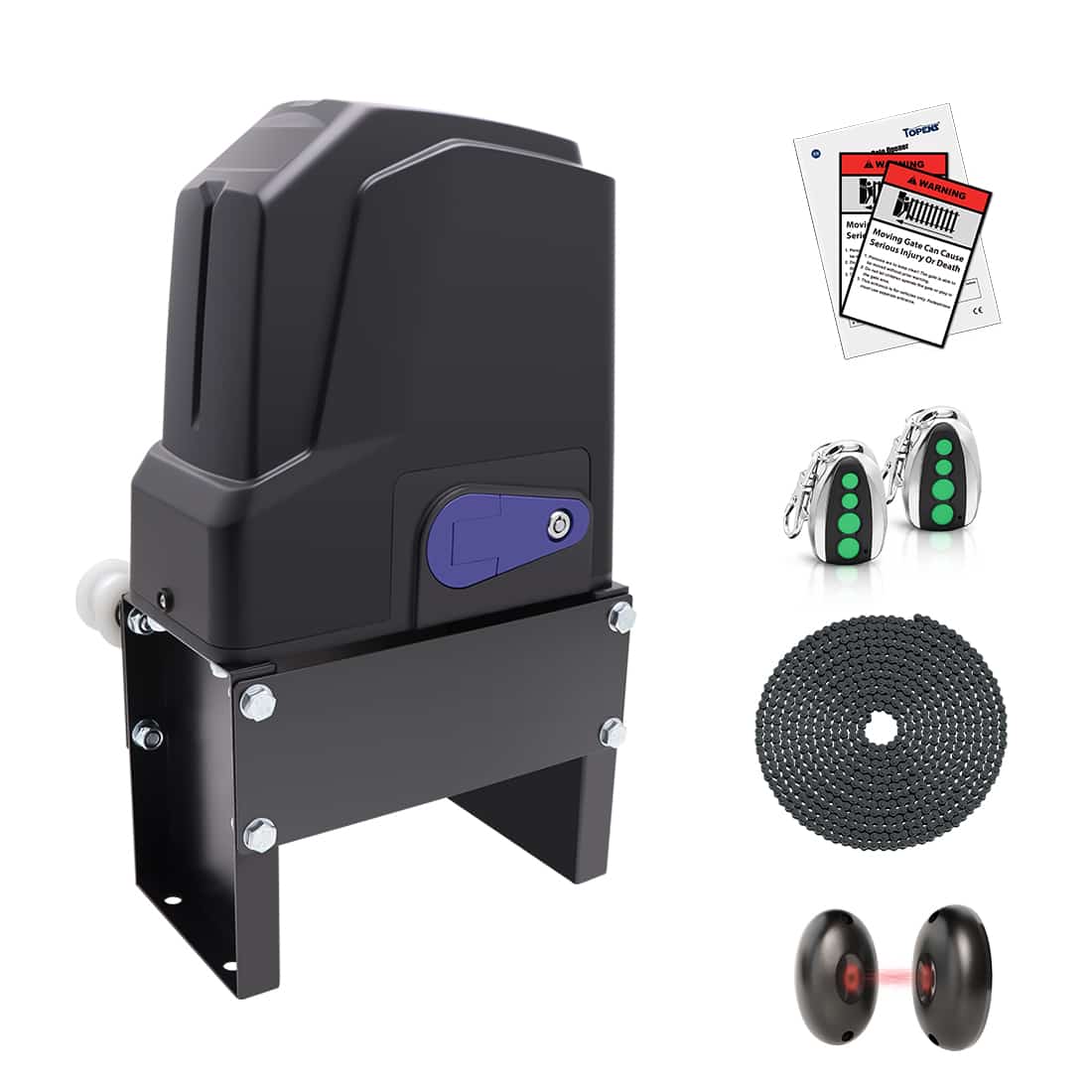
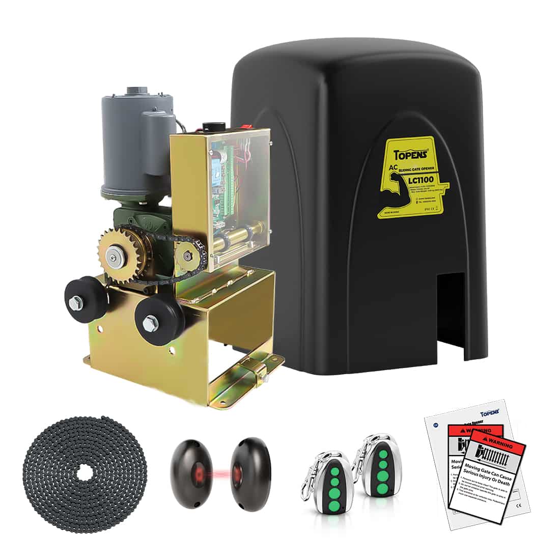
Before starting the installation process, make sure you have the necessary tools and materials at hand: TRF3 retro-reflective photocell sensor kit, screws, wires, wire strippers, cutters, screwdrivers, drills, etc.
Step 2: Determine the Optimal Photocell Location
To ensure reliable operation, the photocell must be positioned correctly.
- Identify a suitable location on both sides of the gate for the sensor installation. Make sure that both the photocell and the reflector are positioned at a suitable height to ensure unobstructed communication between the two units.
- Vertically install the photocell over a height of at least 8” (20cm) with screws.
- The photocell can be installed on either side of the gate.
- Avoid installation during storms with lightning.

Step 3: Wiring and Electrical Connections of the Photocell
- Before proceeding with any wire connections, ensure that the power switch is turned OFF.
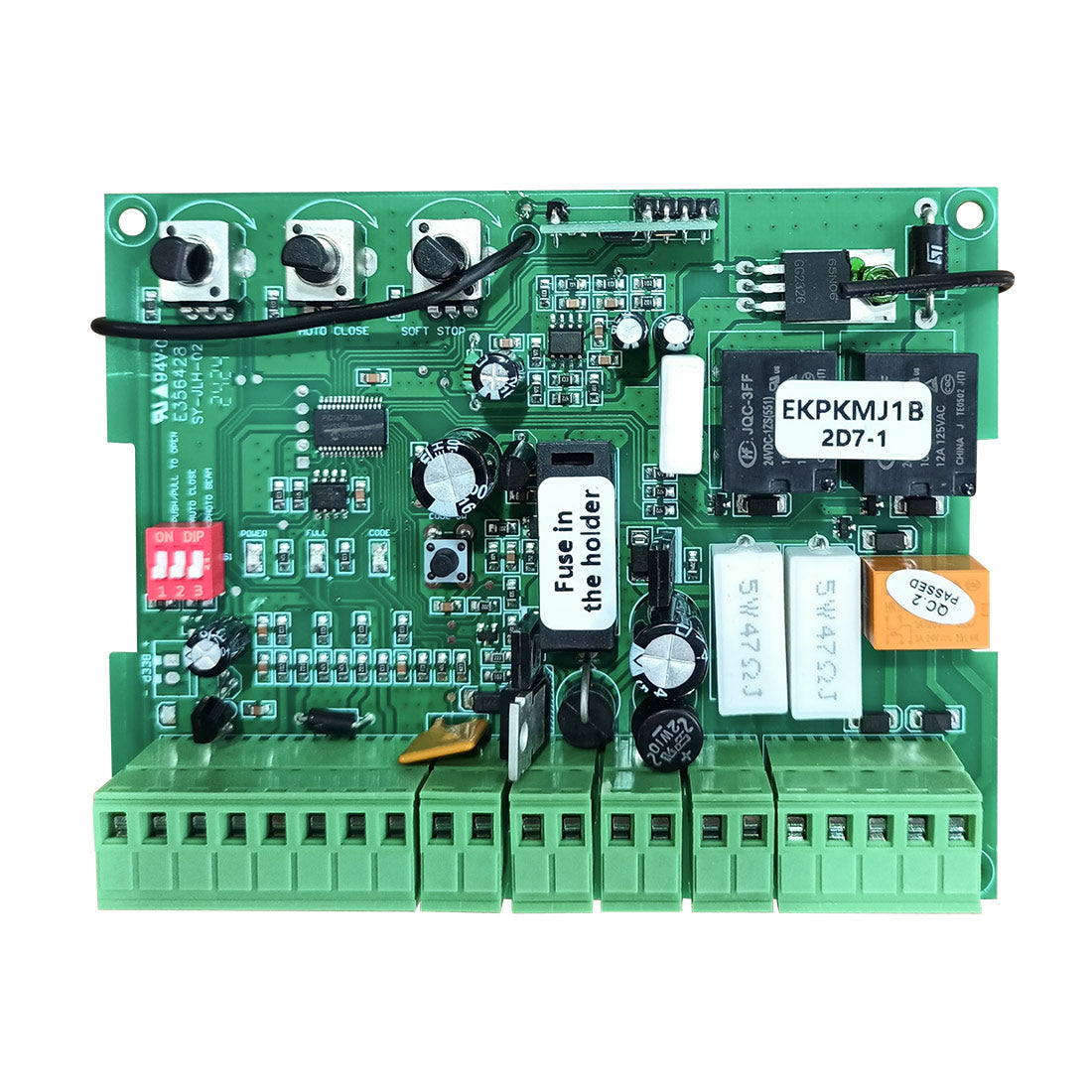
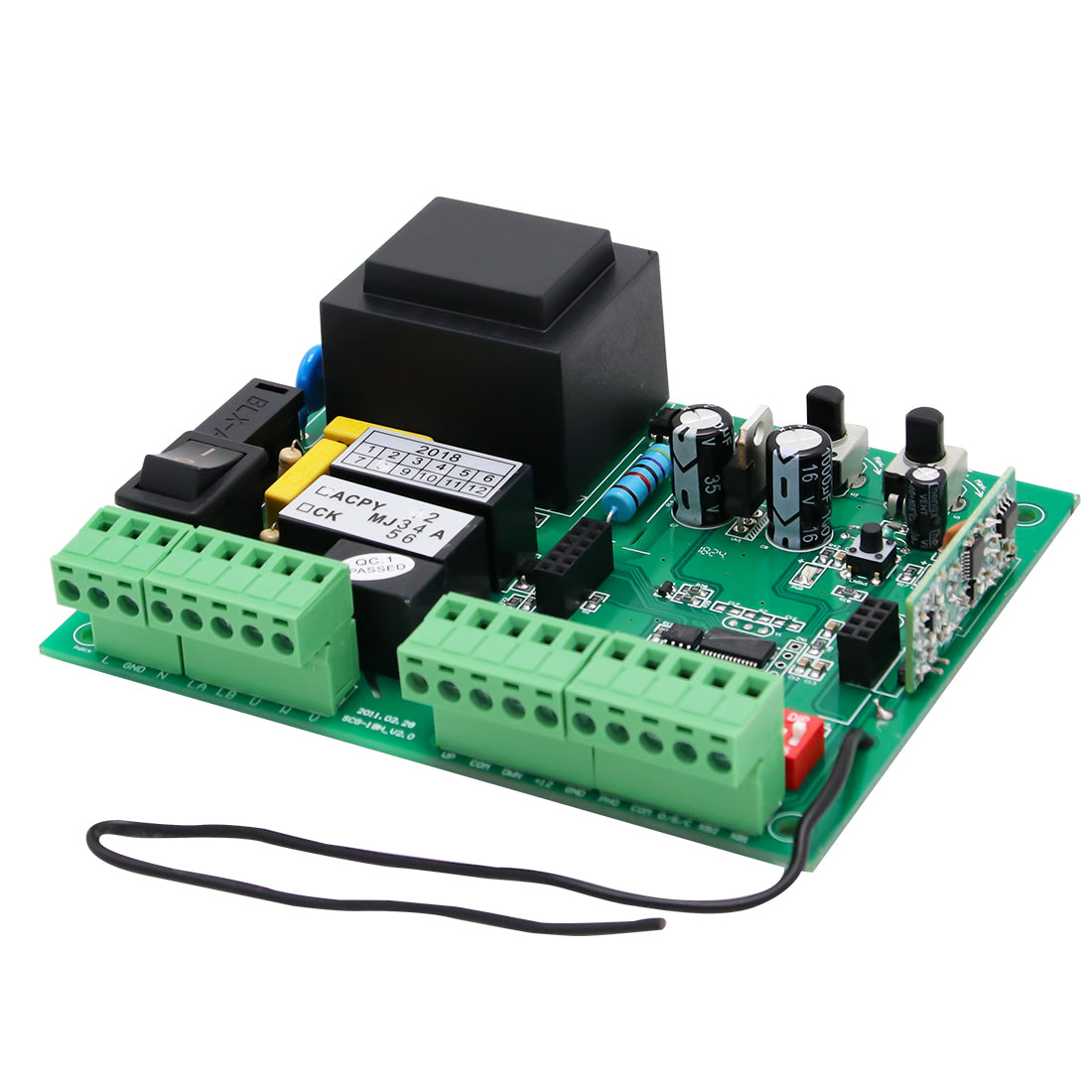
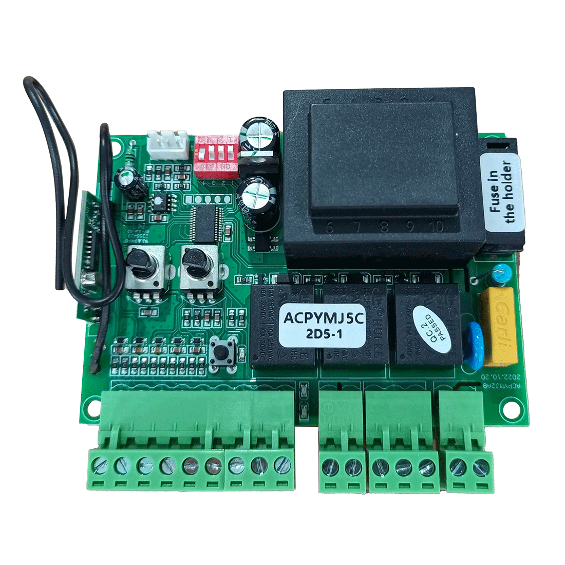
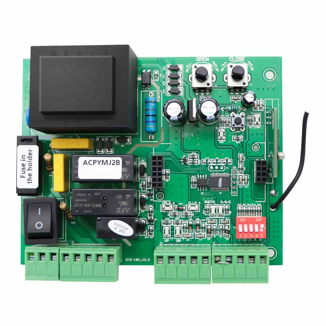
- Locate the appropriate terminals on the gate opener control unit for the photocell connection. Refer to the User Manual of the corresponding gate opener for specific instructions on which terminals to use.

- For other brands of gate opener whose control board accepts “Normal Open or Normal Close Dry Contact” signal, you must confirm which terminal is the power output and which terminal is the photocell input.

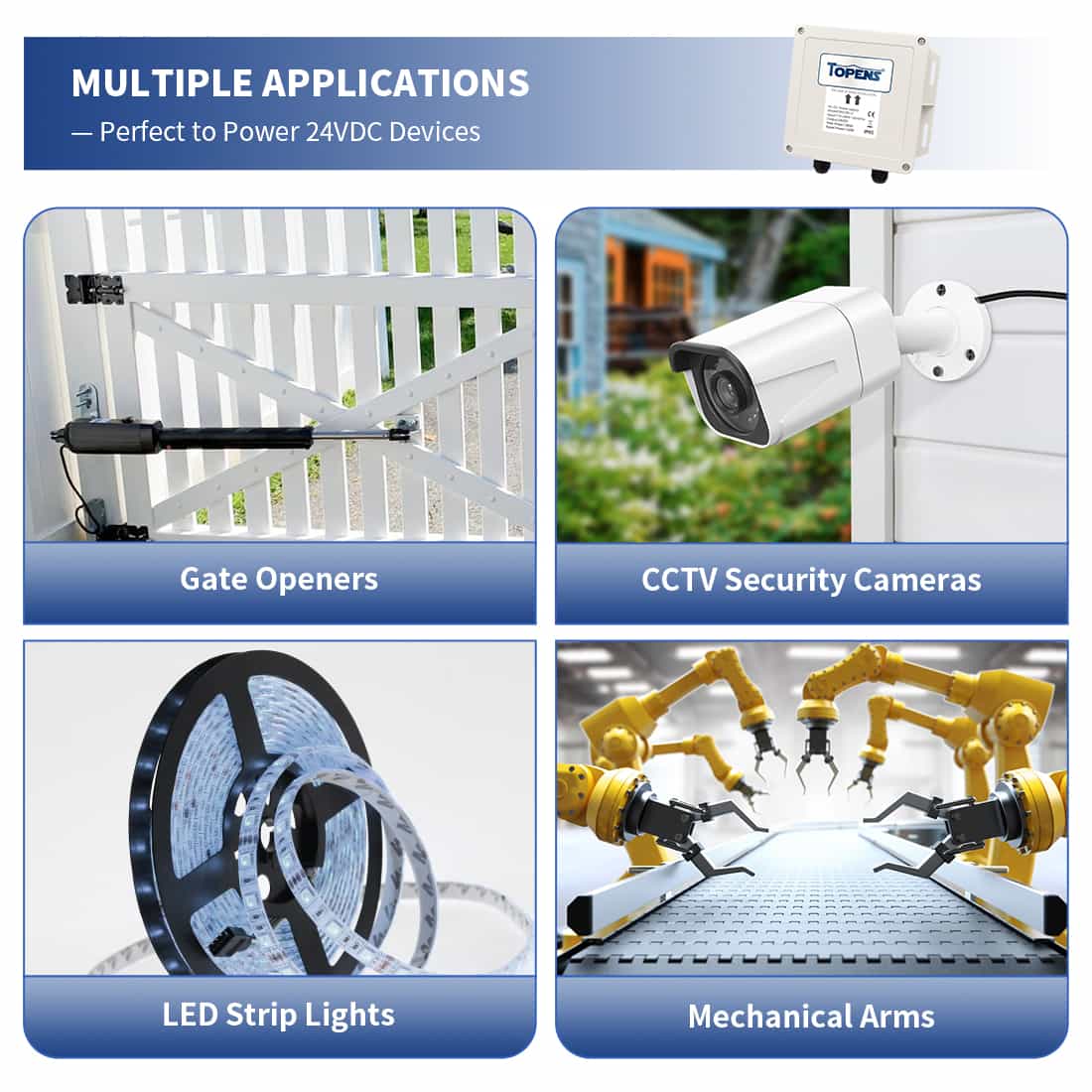
- If the gate opener does not have a 10-25VAC or 12-30VDC AUX. power output, then you should provide a separate power supply for the sensor. DO NOT connect the power supply to a receptacle controlled by an ON/OFF switch.
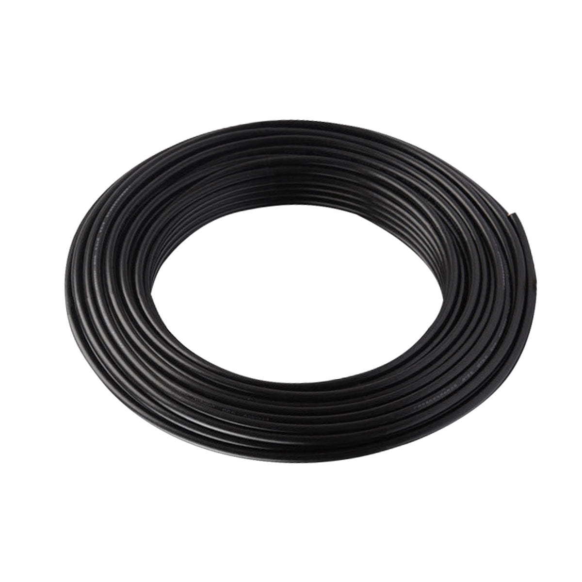
- The cable (size: 4C x 22 AWG) required to connect the infrared photocell to the gate opener is NOT included.
Note: If the photocell terminal on the control board is initially shorted by a wire jumper in the factory, please remove the wire jumper before wiring the photocell terminals to it.
Step 4: Identify the Ideal Reflector Position
- Mount the photocell vertically and wire it BEFORE mounting the reflector.
- Power on to determine the reflector position. Ensure that there is no obstruction between the photocell and the reflector during alignment.
- Position the reflector directly opposite the mounted photocell. The working light on the photocell turns to Green when the reflector is in the correct position. Fine tune the photocell alignment if necessary.
- Fix the reflector with screws to ensure that the working light remains GREEN.
- The photocell has a maximum sensing range of 33ft. (10m).
Note: For some TOPENS swing gate openers (e.g., A3S, A5S, A8(S), A5131, A8131, AT6131(S), AT12131(S), XD551(S), XD851(S), AD5S, AD8S, PW302, PW502, PW802, A5132, A8132, JY9132, AT6132S, AT12132S, XD552(S), XD852(S)), observe the GREEN light with a press of the remote control to confirm the reflector's ideal position.
Step 5: Test for Proper Operation
- Set the control board to turn on the photocell function if needed (Refer to the User Manual of the corresponding gate opener.)
- Activate the gate opener and observe the sensor's functionality.
- Place an obstruction in the sensor beam path to interrupt the infrared beam and verify if the working light turns from GREEN to RED and whether the gate opener responds accordingly, stopping or reversing its operation.
- Double-check the wiring and consult TOPENS customer service for troubleshooting steps if the sensor does not function as expected.
Proper installation of the retro-reflective photocell sensor ensures the safe and efficient operation of your automatic gate opener. Follow this guide to accurately place, wire, and test the sensor, enhancing the safety and convenience of your gate opener system.