When installing a TOPENS swing gate opener, it is crucial to carefully consider the position of the post brackets. Once the post brackets are fixed, both the arm position on the gate and the maximum opening angle of the gate will be settled. By selecting the appropriate mounting position for the post brackets, you can customize the gate's opening angle to suit your specific requirements. Let’s explore the process of determining the position of these mounting hardware components.
Installation Modes and Preparations
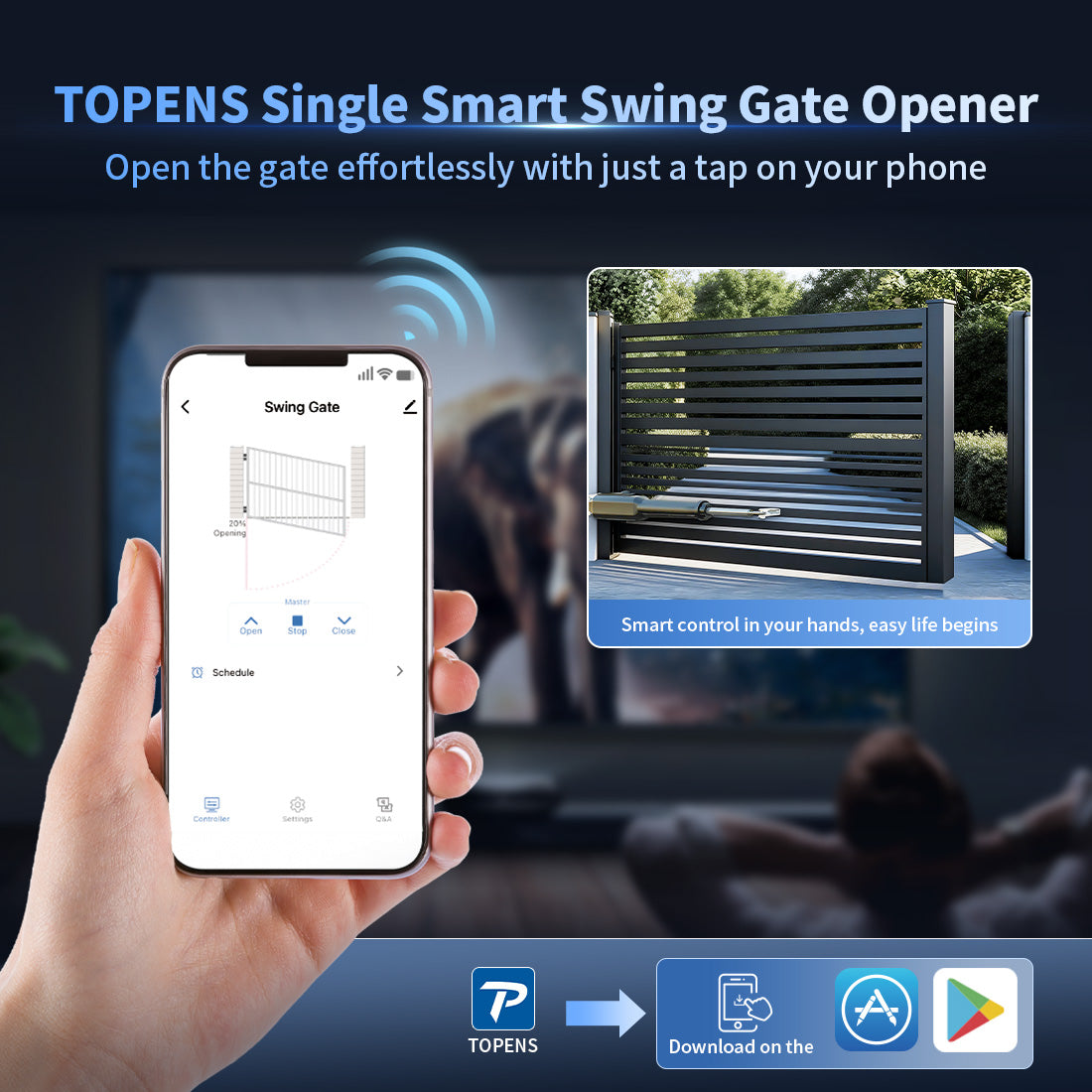
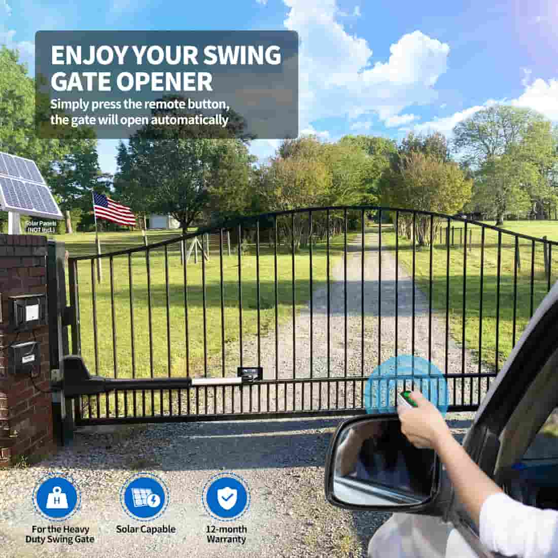
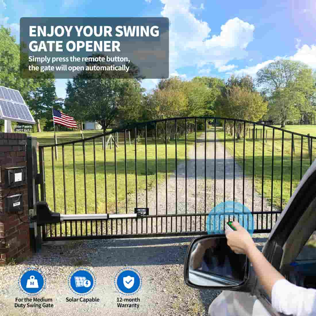
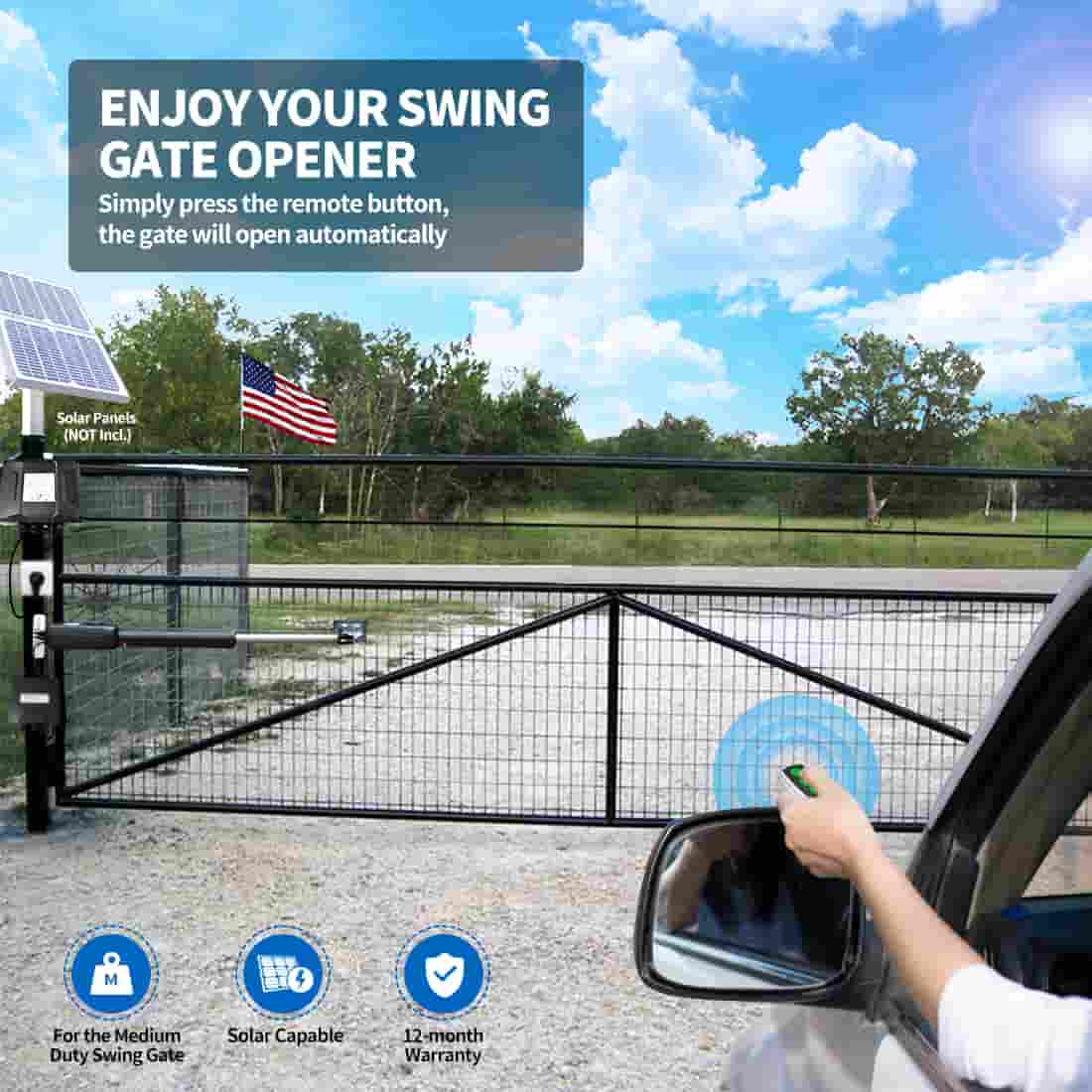
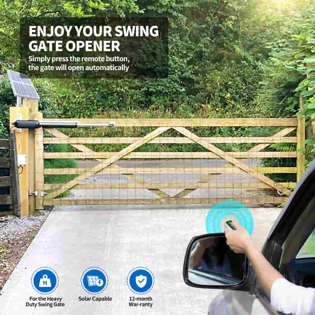
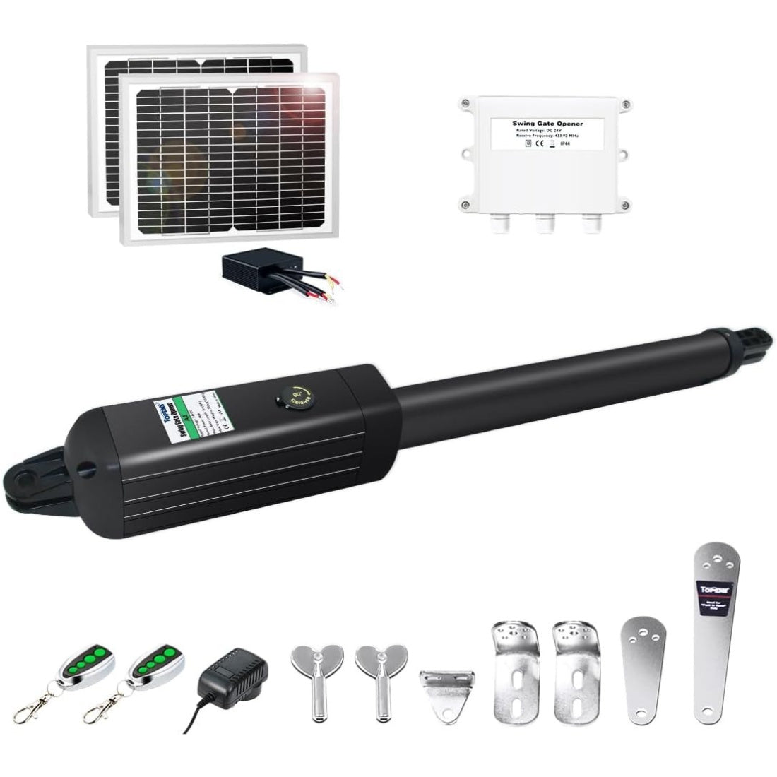
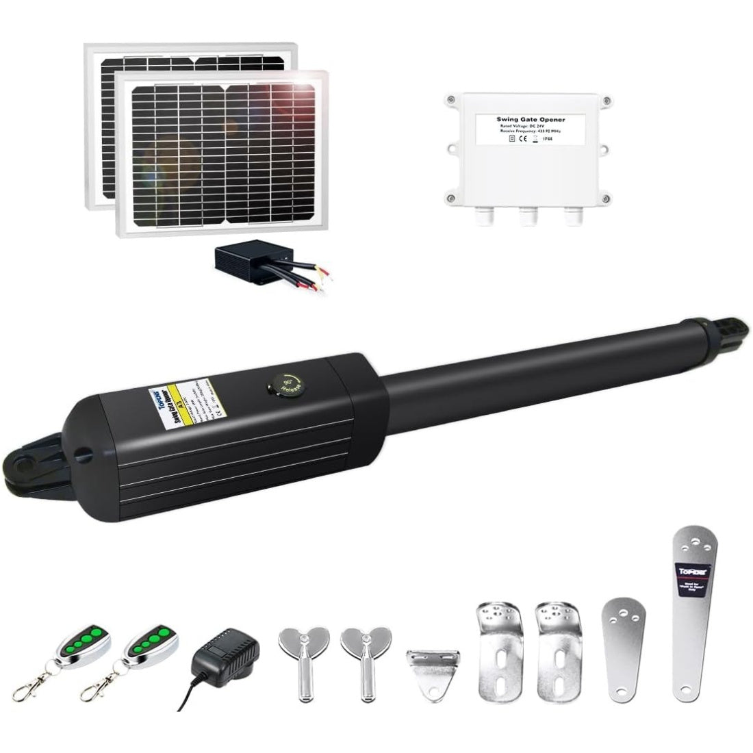
TOPENS swing gate electric opener offers two installation modes: Pull-to-Open and Push-to-Open. Before starting the installation, it is crucial to stress that the gate should NEVER open into public access areas for safety reasons.
Installing Post Brackets (Pull-to-Open Mode)
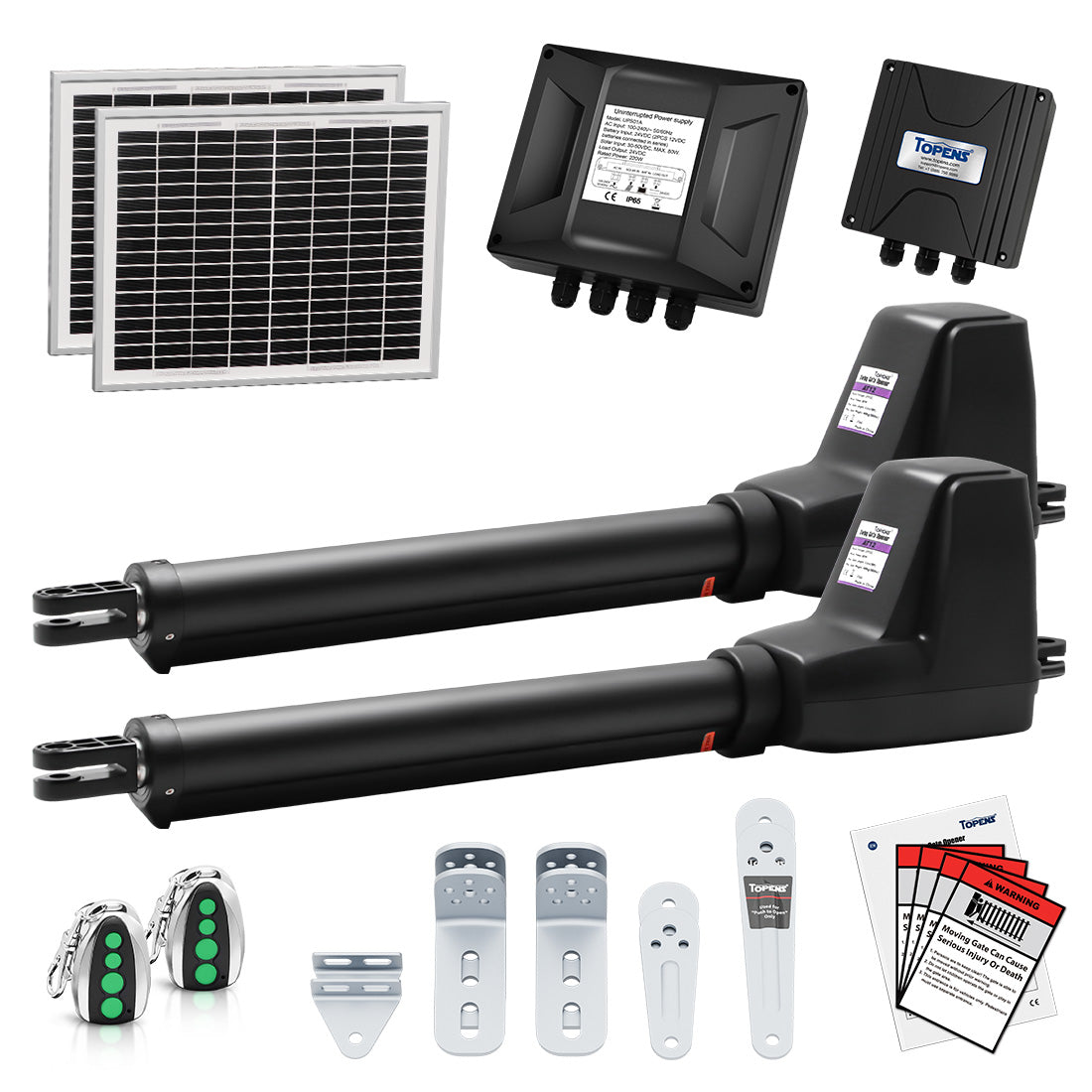
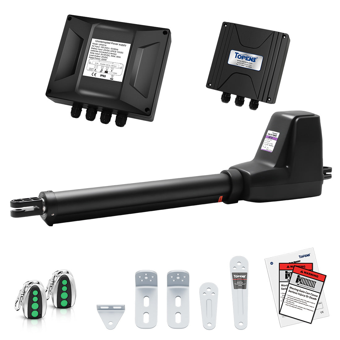
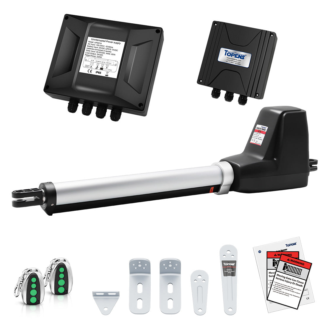
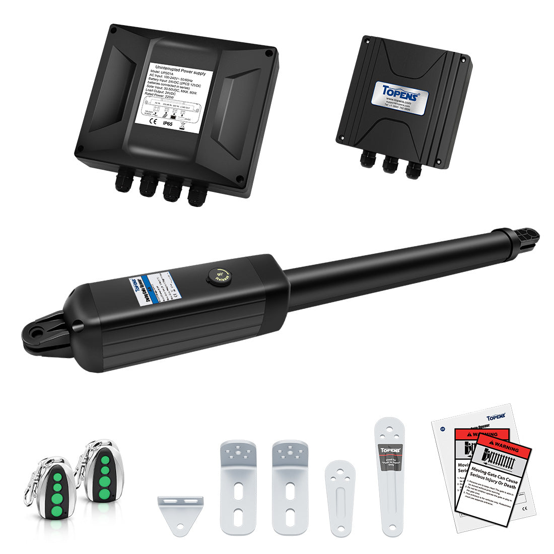
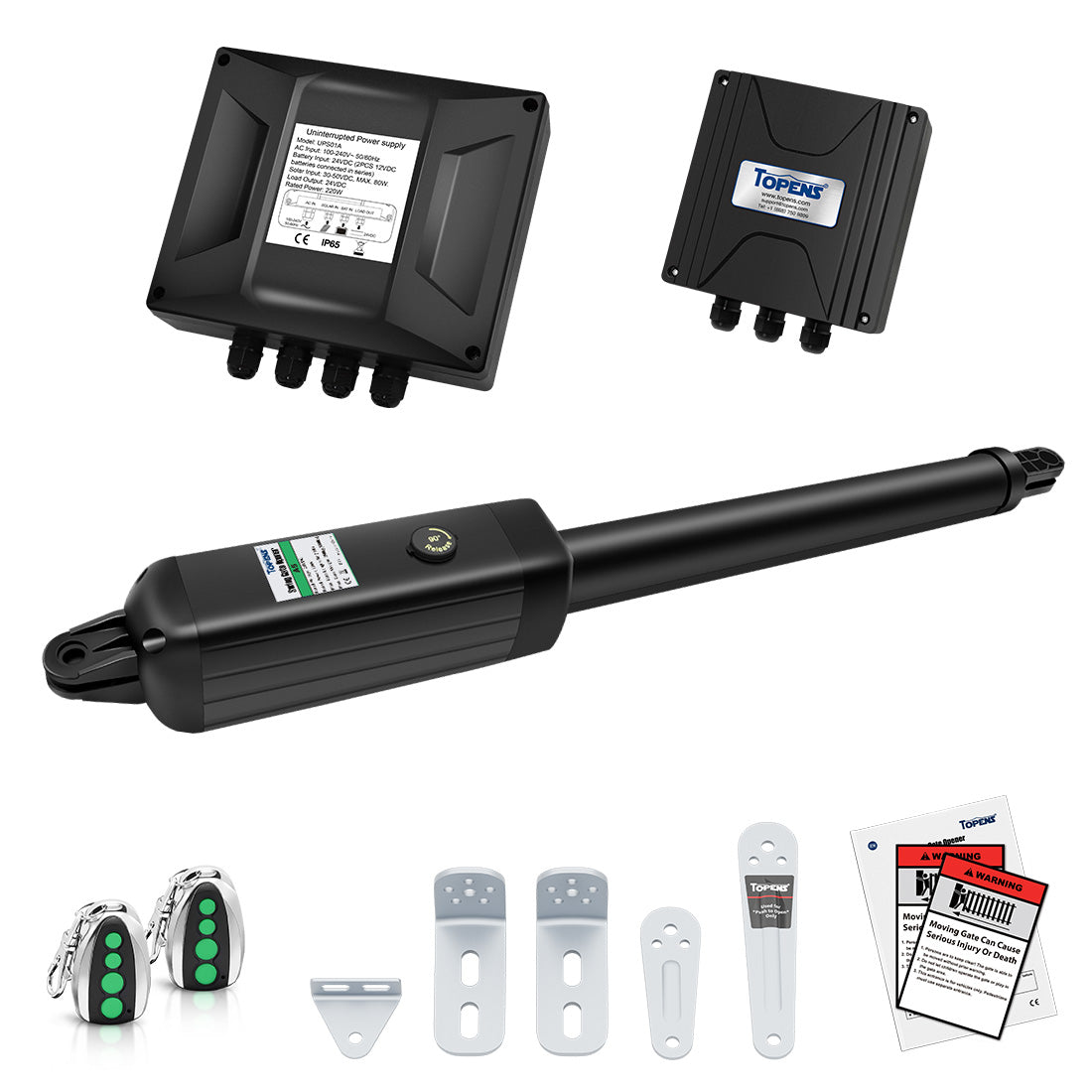
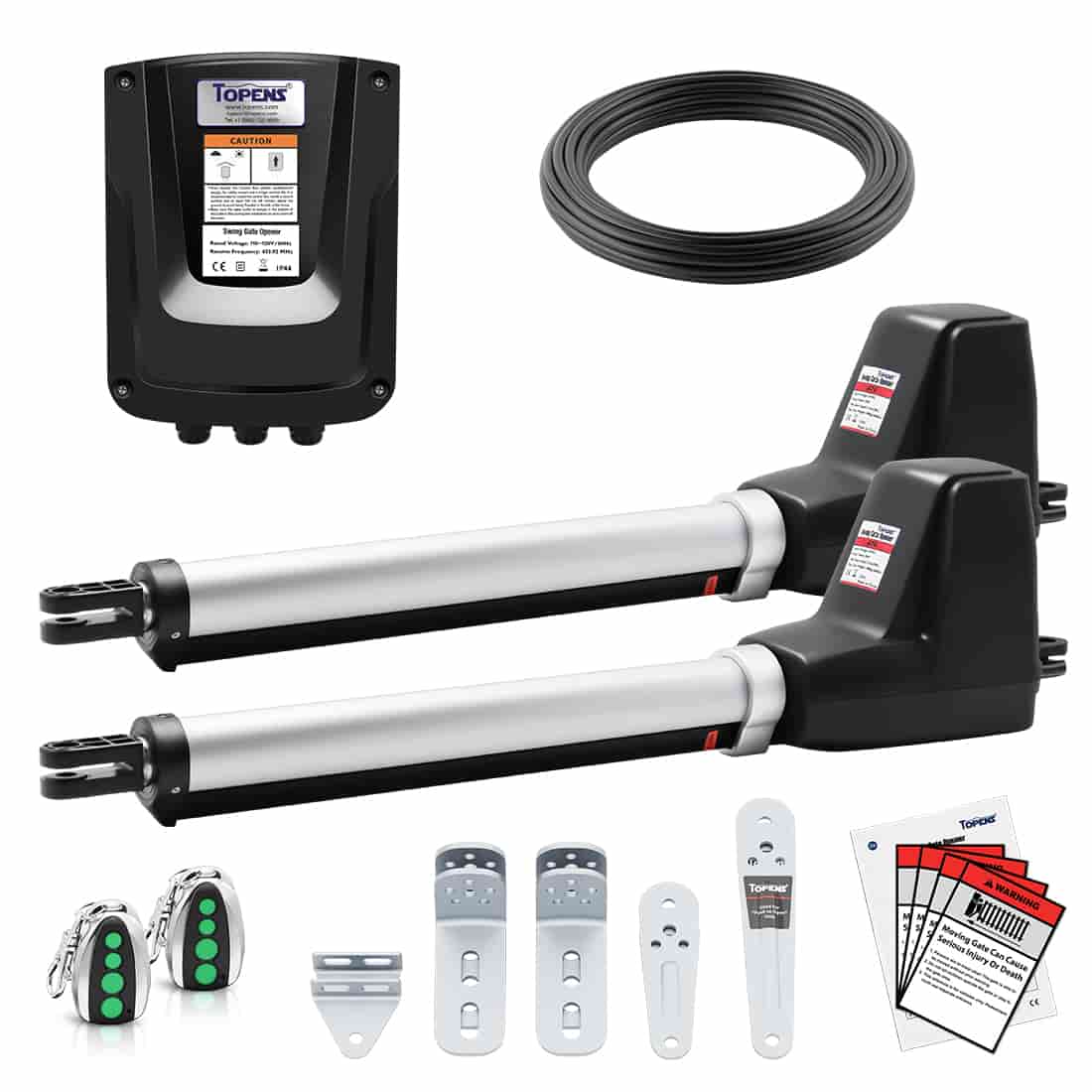
Refer to the user manual of the gate opener (specifically the section "Install the Opener on the Gate - for Pull to Open"), which includes illustrations and tables showing the maximum opening angle of the gate for given measurements A and B. These guidelines will help you determine the correct mounting position for the post brackets. Let's take the TOPENS AT6132S swing gate opener as an example:
In Pull-to-Open installation, for instance, if A is 19cm and B is 15cm, the maximum opening angle of the gate is 106°.

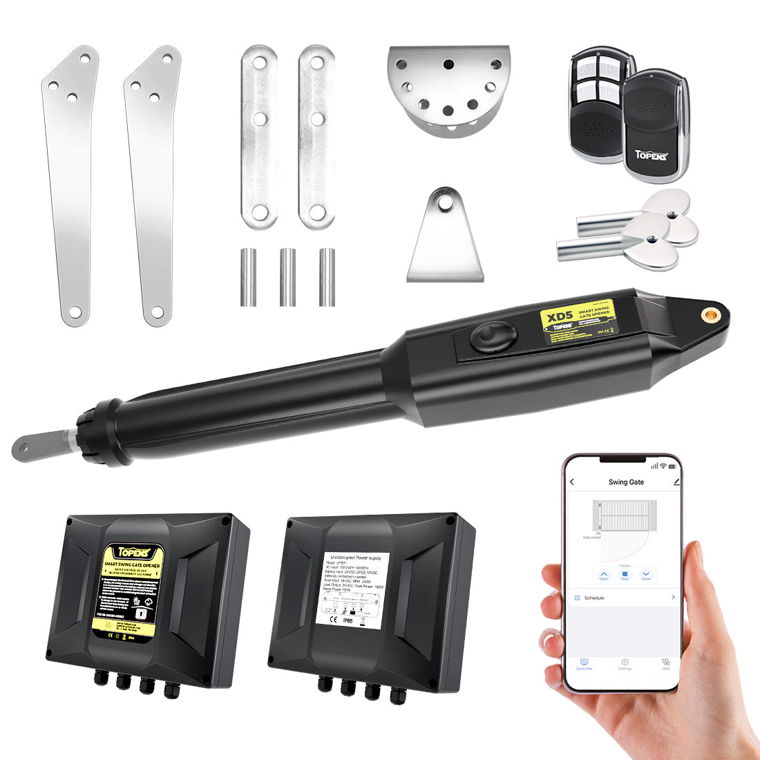
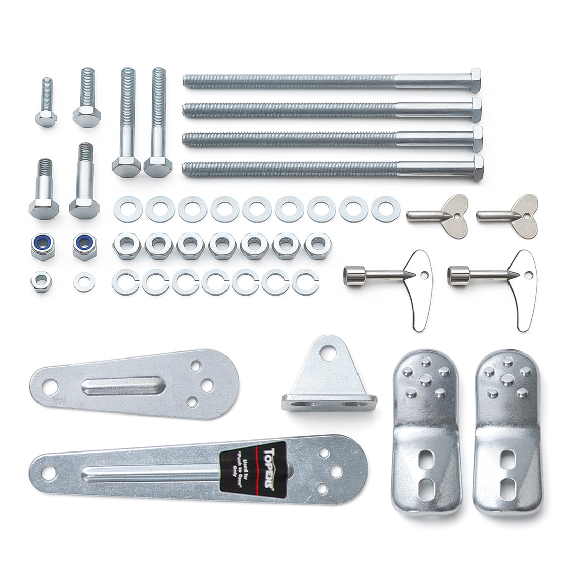
1. Place the post pivot bracket between the two post brackets, and assemble them together using the bolts, washers, and nuts provided. Avoid over-tightening the nuts as the post pivot bracket will need to be adjusted later.
2. Attach the gate bracket and post bracket assembly to the opener by inserting a clevis pin. Secure the clevis pin with a hairpin clip.
3. With the opener arm fully retracted and the gate in a fully open position, place the opener, along with the post bracket assembly and the gate bracket, on the gate post and the gate itself. While holding the gate opener in the horizontal position, temporarily secure the post bracket assembly and the gate bracket to the post and gate using C-clamps.
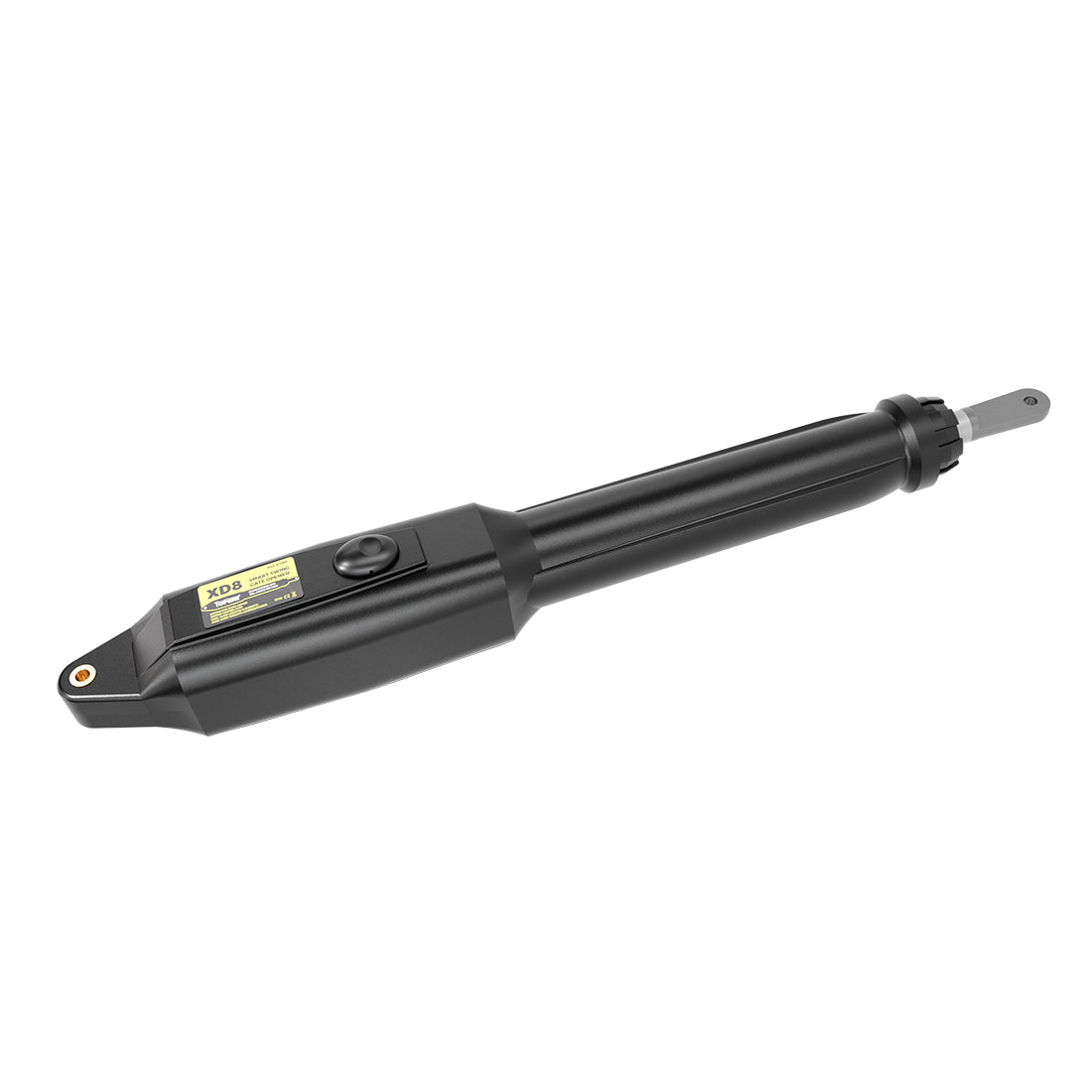
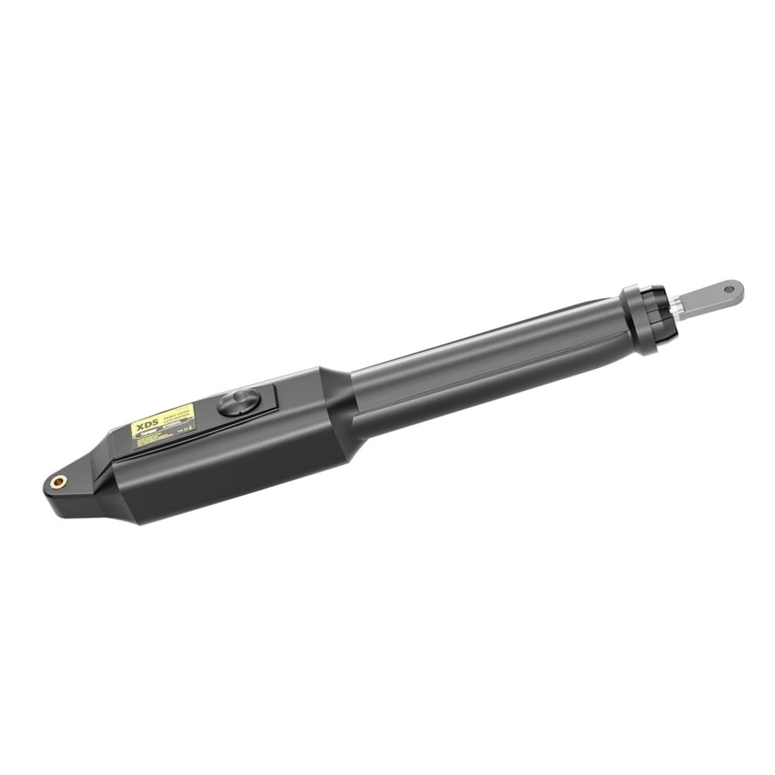
NOTE: The opener has an emergency release design. Use the release key to release the opener. You can manually extend or retract the moving rod by pulling or pushing the front mount. Make sure that the opener is restored to normal operation before activating it.
4. Ensure that the gate opener and brackets allow a minimum clearance of 2.5cm (1") between the gate and the opener in both open and closed positions. This mounting position provides the most efficient leverage point for operation and minimizes pinch areas.
If the required clearance is not met or if the gate opener is binding with the post pivot bracket, you can rotate the post pivot bracket or slightly adjust the position of the post bracket assembly to achieve the proper distance.

5. Mark the positions for the bolt holes on the gate post and the gate, then remove the opener and bracket assemblies by taking off the C-clamps.
6. Drill holes in the marked positions on the post and gate.
7. Securely fasten the post bracket assembly to the gate post and attach the gate bracket to the gate.
Installing Post Brackets (Push-to-Open Mode)
The steps for push-to-open installation mode are identical, with the following exceptions:
- Refer to the user manual’s “Install the Opener on the Gate – for Push to Open” section to determining the proper mounting position for the post brackets.

- Use the PSO Part (Push-to-Open Bracket) instead of the post pivot bracket.
- Before identifying the temporary position of the brackets in Step Three, ensure that the opener arm is fully retracted and the gate is in the fully closed position.

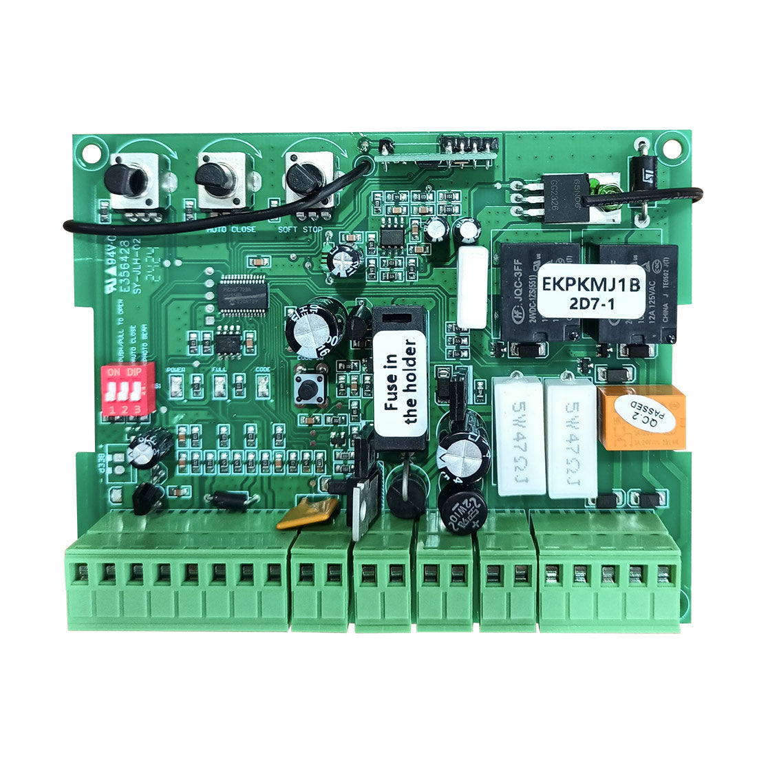
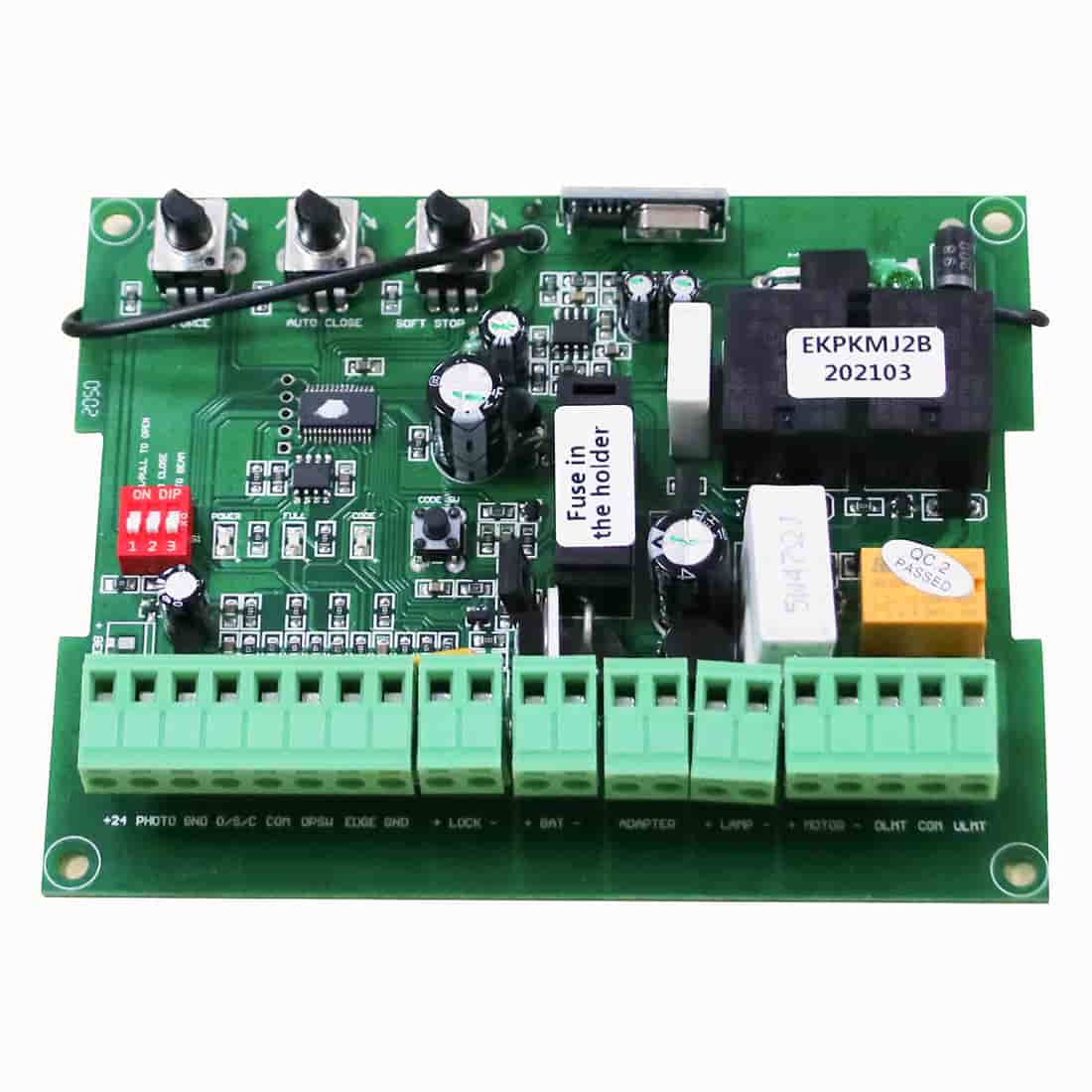
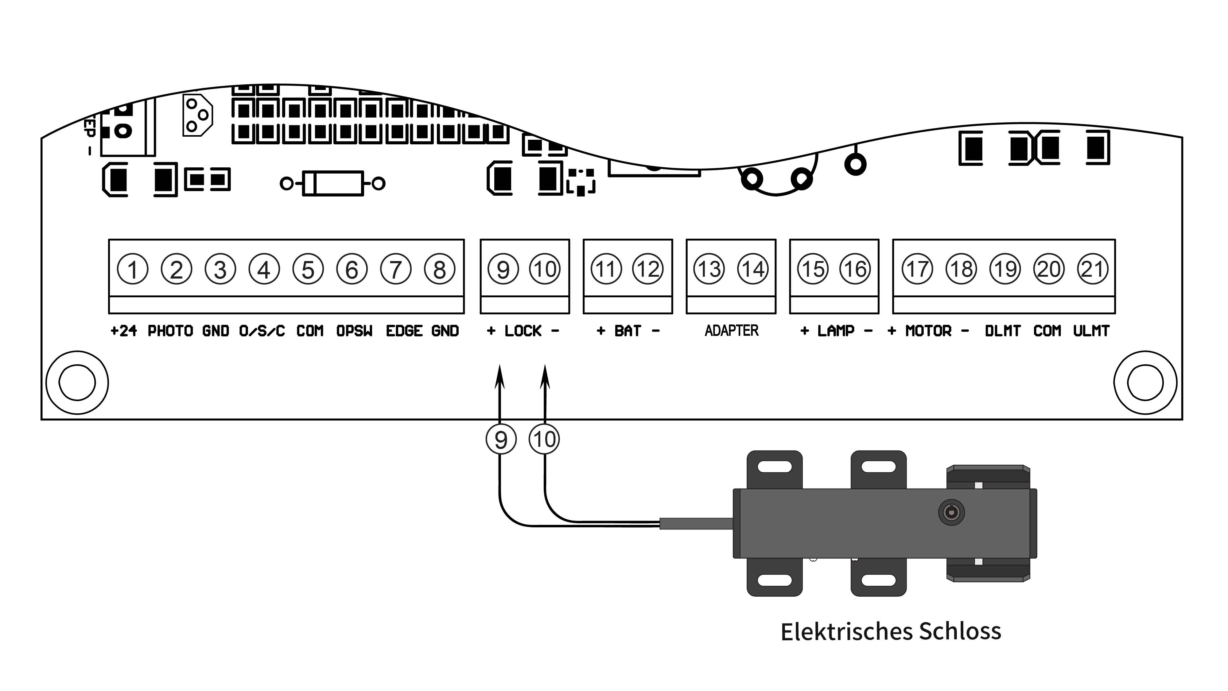
NOTE: Make sure that the wire connection of the actuator or the setting of the DIP Switch on the control board is consistent with the Pull/Push-to-Open installation.
Proper installation of the mounting hardware determines your maximum opening angle of the gate. Still have questions? Leave a message for us and our friendly technical support team is standing by to assist with your project.